


OMNI 4000/7000 Operations and Maintenance Guide
– Rev F
7-51
Maintenance
Add, Remove and Replace Modules
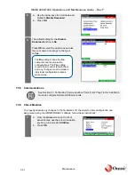
1.
If you are using the panel mount chassis,
lift the Front Panel Bezel upwards to slide
the inner chassis out.
If you are using the NEMA chassis, remove
the card-retaining bracket from the chassis.
2.
Use the card ejector to remove the module
from the chassis.
Make note of the module’s designated slot
number on the motherboard.
If removing a CPU or power supply card, there will be cables to disconnect before
you are able to remove the card from the chassis. Remember to re-connect these
cables when putting in the new cards.
3.
Insert the new module into its designated
slot.
4.
To reinstall the panel mount chassis,
slowly slide the inner chassis back into the
flow computer.
For the NEMA chassis, re-install the
card-retaining bracket.
If you have added a module, removed a module or changed the order of the
modules, go to the back panel wiring tables in Section 3.7 Connect to Field Devices
in the Installation Guide to verify or re-configure the wiring.
If you have replaced a module (with the same type of module), the back panel
wiring does not change.
5.
Power up the flow computer.
6.
Go to Section 7.3.9 Check Modules and
follow the instructions to complete the
Check Modules
feature. If any module
indicates a
N
for NO under the Hardware
or Software column, execute the
Check
Modules
feature until all modules indicate
Y
for YES under both columns.
Содержание 4000 Series
Страница 1: ...Series 4000 7000 Operations Maintenance Guide...
Страница 21: ...OMNI 4000 7000 Operations and Maintenance Guide Rev F 2 4 OMNI 4000 7000 Overview Figure 2 2 OMNIPANEL...
Страница 23: ...OMNI 4000 7000 Operations and Maintenance Guide Rev F 2 6 OMNI 4000 7000 Overview Figure 2 4 OMNI Modbus Tester...


