3 8 Process Alarms
3 8 Process Alarms
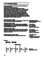
A process alarm allows for an absolute trigger level or specific temperature
to be monitored. When the
process exceeds that absolute trigger level
an alarm occurs. A process alarm is independent of the set point.
Adjust A1FN (Alarm 1 function) in the setup menu. One of 8 functions can be
selected for process alarm. When PV1.H or PV1.L is selected, the alarm
monitors the PV1 value. When PV2.H or PV2.L is selected the alarm
monitors the PV2 value. When P1.2.H or P1.2.L is selected the alarm
trips if the PV1 or PV2 value exceeds the trigger level. When D1.2.H or
D1.2.L is selected, the alarm occurs if the PV1-PV2 (difference) value exceeds
the trigger level. The trigger level is determined by A1SP (Alarm 1 set point)
and A1HY (Alarm 1 hysteresis value) in the User Menu for alarm 1. The hysteresis
value is designed to prevent interference action of the alarm in a noisy environment.
Normally A1HY can be set with a minimum ( 0.1 ) value.
When a normal alarm is selected, the alarm output is de-energized in the
non-alarm condition and energized in an alarm condition.
If a latching alarm is selected, once the alarm output is energized, it will
remain unchanged even if the alarm condition is cleared. The latching alarms
are disabled when the power is shut off or if event input is applied with proper
selection of EIFN(event input function).
A holding alarm prevents an alarm from power up. The alarm is enabled
only when the process reaches the set point value ( may be SP1 or SP2,
See
event input ). Afterwards, the alarm performs the same
function as a normal alarm.
Normal Alarm : A1MD = NORM
Latching Alarm : A1MD = LTCH
Holding Alarm : A1MD = HOLD
section 4-1
205
195
205
195
205
205
205
195
195
195
ON
OFF
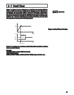
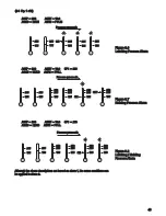
Figure 3.5
Normal Process Alarm
Figure 3.5
Normal Process Alarm
A1SP = 200
A1HY = 10.0
A1MD = NORM
A1FN = PV1.H
A1SP = 200
A1HY = 10.0
A1MD = NORM
A1FN = PV1.H
Process proceeds
Process proceeds
Examples:
Latching / Holding Alarm : A1MD = LT.HO
A latching / holding alarm performs both holding and latching function.
Latching / Holding Alarm : A1MD = LT.HO
A latching / holding alarm performs both holding and latching function.
Process Alarm 1
Process Alarm 1
Setup : A1FN, A1MD
Setup : A1FN, A1MD
Adjust : A1SP, A1HY
Adjust : A1SP, A1HY
Process Alarm 2
Process Alarm 2
Setup : OUT2, A2FN, A2MD
Setup : OUT2, A2FN, A2MD
Adjust : A2SP, A2HY
Adjust : A2SP, A2HY
Trigger level = A1SP 1/2 A1HY
A
Trigger level = A1SP 1/2 A1HY
A
Trigger level = A2SP 1/2 A2HY
A
Trigger level = A2SP 1/2 A2HY
A
Reset Latching alarm
Reset Latching alarm
1. Power off
1. Power off
2. Apply Event input in accordance
2. Apply Event input in accordance
with proper selection of EIFN
with proper selection of EIFN
8 Types of Process Alarms :
PV1.H, PV1.L, PV2.H, PV2.L, P1.2.H,
P1.2.L, D1.2.H, D1.2.L
8 Types of Process Alarms :
PV1.H, PV1.L, PV2.H, PV2.L, P1.2.H,
P1.2.L, D1.2.H, D1.2.L
48

