2 6 Thermocouple Input Wiring
2 6 Thermocouple Input Wiring
+
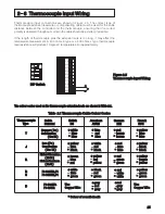
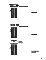
Figure 2.5
Thermocouple Input Wiring
Figure 2.5
Thermocouple Input Wiring
The colour codes used on the thermocouple extension leads are shown in Table 2.1.
The colour codes used on the thermocouple extension leads are shown in Table 2.1.
Thermocouple
Type
Thermocouple
Type
Cable
Material
Cable
Material
British
BS
British
BS
American
ASTM
American
ASTM
German
DIN
German
DIN
French
NFE
French
NFE
T
J
Copper ( Cu )
Constantan
( Cu-Ni )
Copper ( Cu )
Constantan
( Cu-Ni )
+ blue
red
* blue
+ blue
red
* blue
+ red
brown
* brown
+ red
brown
* brown
+ yellow
blue
* blue
+ yellow
blue
* blue
Iron ( Fe )
Constantan
( Cu- Ni )
Iron ( Fe )
Constantan
( Cu- Ni )
+ white
red
* black
+ white
red
* black
+ red
blue
* blue
+ red
blue
* blue
+ yellow
black
* black
+ yellow
black
* black
K
Nickel-Chromium
( Ni-Cr )
Nickel-Aluminum
( Ni-Al )
Nickel-Chromium
( Ni-Cr )
Nickel-Aluminum
( Ni-Al )
+ brown
blue
* red
+ brown
blue
* red
+ yellow
red
* yellow
+ yellow
red
* yellow
+ red
green
* green
+ red
green
* green
+ yellow
purple
* yellow
+ yellow
purple
* yellow
R
S
R
S
Pt-13%Rh,Pt
Pt-10%Rh,Pt
Pt-13%Rh,Pt
Pt-10%Rh,Pt
+ white
blue
* green
+ white
blue
* green
+ black
red
* green
+ black
red
* green
+ red
white
* white
+ red
white
* white
+ yellow
green
* green
+ yellow
green
* green
B
Pt-30%Rh
Pt-6%Rh
Pt-30%Rh
Pt-6%Rh
+grey
red
* grey
+grey
red
* grey
Table 2.1 Thermocouple Cable Colour Codes
Table 2.1 Thermocouple Cable Colour Codes
* Colour of overall sheath
* Colour of overall sheath
+ white
blue
* blue
+ white
blue
* blue
+ yellow
blue
* black
+ yellow
blue
* black
1
2
3
4
ON
DIP Switch
DIP Switch
Use
Copper Wire
Use
Copper Wire
Use
Copper Wire
Use
Copper Wire
+red
grey
* grey
+red
grey
* grey
25
1
2
3
4
5
6
7
8
9
10
11
12
13
14
15
16
17
18
19
20
If the length of thermocouple plus the extension wire is too long, it may affect the
temperature measurement. A 400 ohms K type or a 500 ohms J type thermocouple
lead resistance will produce 1 degree C temperature error approximately.
Thermocouple input connections are shown in Figure 2.5. The correct type of
thermocouple extension lead-wire or compensating cable must be used for the entire
distance between the controller and the thermocouple, ensuring that the correct
polarity is observed throughout. Joints in the cable should be avoided, if possible.


