3 17 Bumpless Transfer
3 17 Bumpless Transfer
The bumpless transfer function is available for output 1 and output 2 ( provided
that OUT2 is configured as COOL ).
is enabled by selecting BPLS for O1FT and/or O2FT and
activated as one of the following cases occurs :
1. Power starts ( within 2.5 seconds ).
2. The controller enters the failure mode. See section 3-16 for failure mode
descriptions.
3. The controller enters the manual mode. See section 3-22 for manual mode
descriptions.
4. The controller enters the calibration mode. See chapter 6 for calibration
mode descriptions.
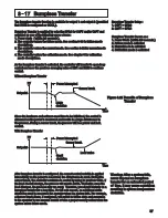
As the bumpless transfer is activated, the controller will transfer to open-loop
control and uses the previous averaging value of MV1 and MV2 to continue
control.
Bumpless Transfer
Without Bumpless Transfer
Without Bumpless Transfer
With Bumpless Transfer
With Bumpless Transfer
Power interrupted
Power interrupted
Power interrupted
Power interrupted
Large
deviation
Large
deviation
Small
deviation
Small
deviation
Sensor break
Sensor break
Sensor break
Sensor break
Time
Time
Set point
Set point
Set point
Set point
PV
PV
Load varies
Load varies
Since the hardware and software need time to be initialized, the control is
abnormal as the power is recovered and results in a large disturbance to
the process. During a sensor break, the process will lose power and lack
control.
Since the hardware and software need time to be initialized, the control is
abnormal as the power is recovered and results in a large disturbance to
the process. During a sensor break, the process will lose power and lack
control.
After bumpless transfer is configured, the correct control variable is applied
immediately as the power is recovered, the disturbance is small. During the
sensor break, the controller continues to control by using its previous value. If
the load doesn't change, the process will remain stable. Thereafter, once the
load changes, the process may run away.
For fail safe reason, an additional alarm
should be used to announce the operator when the system fails. For
,
a Sensor Break Alarm, if configured, will switch to failure state and announce
to the operator to use manual control or take a proper security action when the
system enters failure mode.
Therefore, you should not rely on a
bumpless transfer for a long time.
example
Bumpless Transfer Setup :
1. O1FT = BPLS
2. O2FT = BPLS
Bumpless Transfer Setup :
1. O1FT = BPLS
2. O2FT = BPLS
Bumpless Transfer Occurs as :
1. Power Starts ( within 2.5 seconds )
2. Failure mode is activated
3. Manual mode is activated
4. Calibration mode is activated
Bumpless Transfer Occurs as :
1. Power Starts ( within 2.5 seconds )
2. Failure mode is activated
3. Manual mode is activated
4. Calibration mode is activated
Figure 3.21 Benefits of Bumpless
Transfer
Figure 3.21 Benefits of Bumpless
Transfer
57
Warning: After a system fails,
never depend on bumpless
transfer for an extended period
of time, it may cause a problem
resulting in system temperature
deviation.
Warning: After a system fails,
never depend on bumpless
transfer for an extended period
of time, it may cause a problem
resulting in system temperature
deviation.

