background image

5 9 Dual Set Point / PID

5 9 Dual Set Point / PID

The ETR-8300 will switch between the two PID sets based on the process
value, the set point or the event input. As the control ramps up to a higher
process value, the process characteristics can change. As this happens, the
original PID values are no longer valid. To achieve optimal control over the
entire range, a second PID set is used.

Example 1: Single Set Point / Dual PID

Example 1: Single Set Point / Dual PID

A heat treating furnace is used over the range of 400 °C to 1200 °C.

A heat treating furnace is used over the range of 400 °C to 1200 °C.

( 1 ) Set the following parameters in the Setup menu:

( 1 ) Set the following parameters in the Setup menu:

FUNC= FULL
A1FN= PV1H
A1MD= NORM
EIFN= PID2
PVMD= PV1
SPMD= MINR

FUNC= FULL
A1FN= PV1H
A1MD= NORM
EIFN= PID2
PVMD= PV1
SPMD= MINR

( 2 ) Adjust the following parameters in the User menu:

( 2 ) Adjust the following parameters in the User menu:

A1SP= 800 °C
A1HY= 1.0 °C
Pl1= 100 ( % )
RAMP: According to the process requirement
SP1: According to the process requirement

A1SP= 800 °C
A1HY= 1.0 °C
Pl1= 100 ( % )
RAMP: According to the process requirement
SP1: According to the process requirement

( 3 ) Lastly, tune PID set one with a SP1= 500 °C, then tune the second PID set with

a SP1=1100 °C, or set the proper values for PB1, Ti1, TD1, PB2, TI2 and TD2
according to previously existing records to eliminate the need for auto-tuning.

( 3 ) Lastly, tune PID set one with a SP1= 500 °C, then tune the second PID set with

a SP1=1100 °C, or set the proper values for PB1, Ti1, TD1, PB2, TI2 and TD2
according to previously existing records to eliminate the need for auto-tuning.

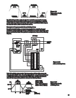
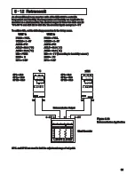
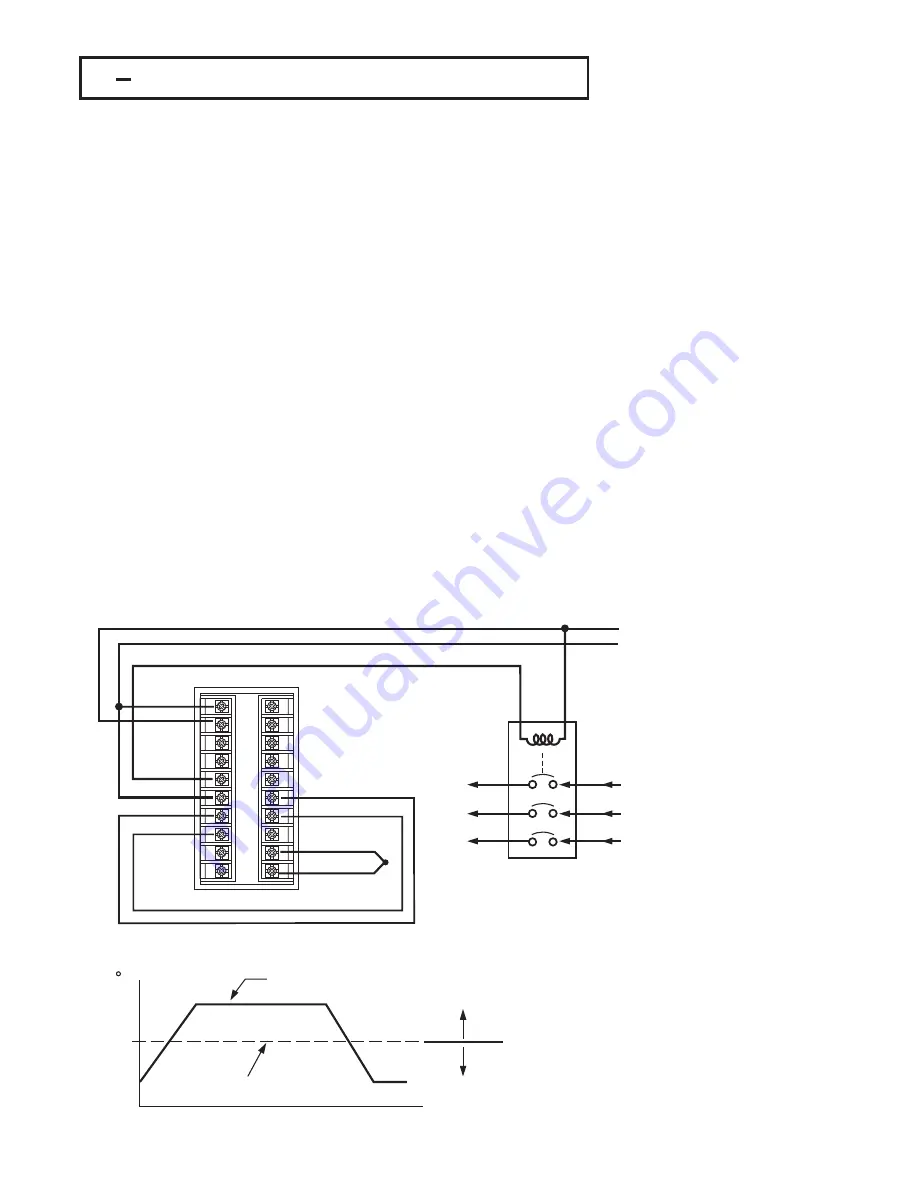
The circuit diagram and its temperature profile are shown as follows :

The circuit diagram and its temperature profile are shown as follows :

To
Furnace
Heater

To
Furnace
Heater

Heater
Power
Input

Heater
Power
Input

AC power

AC power

Alarm 1 controls
Event input

Alarm 1 controls
Event input

Figure 5.14

Figure 5.14

Dual PID Furnace

Dual PID Furnace

Process Value

Process Value

PID Crossover Value

PID Crossover Value

Use PID 1

Use PID 1

Use PID 2

Use PID 2

Time

C

800

Figure 5.15

Figure 5.15

Dual PID Crossover

Dual PID Crossover

94

1

2

3

4

5

6

7

8

9

10

11

12

13

14

15

16

17

18

19

20

Содержание ETR-8300

Страница 1: ...PK488 OMC57 Model ETR 8300 Microprocessor Based SMARTER LOGIC Temperature Control INSTRUCTION MANUAL SMARTER SMARTER LOGIC LOGIC LOGIC...

Страница 2: ...ting procedure practice or the like which if not correctly performed or adhered to could result in personal injury or damage to or destruction of part or all of the product and system Do not proceed b...

Страница 3: ...4 Programming the Full Function Chapter 4 Programming the Full Function 4 1 Event Input 4 2 Second Set Point 4 3 Second PID Set 4 4 Ramp Dwell 4 5 Remote Set Point 4 6 Differential Control 4 7 Output...

Страница 4: ...ss disturbance to the process during tuning and can be used any time The ETR 8300 ETR 8300 18 bit A to D fast sampling rate ETR 8300 is powered by a 90 264 VAC or 11 26 VAC VDC supply incorporating du...

Страница 5: ...PID control It controls the system based on experience and does not need to analyze process metrics as does PID 5 Digital communications RS 485 RS 232 or 4 20 mA retransmission are available as an ad...

Страница 6: ...es Control Stability Figure 1 2 Fuzzy PID Enhances Control Stability 6 PID Fuzzy Control has been proven to be an efficient method to improve process stability as shown by the comparison curves below...

Страница 7: ...utput 1A 240VAC SSR C Pulsed voltage to drive SSR 14V 30mA 0 None 1 Relay 2A 240VAC 2 Pulsed voltage to drive SSR 5V 30mA 3 Isolated 4 20mA 0 20mA 4 Isolated 1 5V 0 5V 5 Isolated 0 10V 6 Triac Output...

Страница 8: ...n the unit leaves the factory the DIP switch is set so that TC RTD are selected for input 1 and all parameters are unlocked Lockout function is used to disable the adjustment of parameters as well as...

Страница 9: ...ocedure Select the parameter in a reverse sequence during menu scrolling Select the operation Mode in sequence Reset the front panel display to a normal display mode also used to leave the specific Mo...

Страница 10: ...diagram shows that the unit has been used for 23456 2 hours since production 10 Figure 1 5 Display Sequence of Initial Message Figure 1 5 Display Sequence of Initial Message Program Code Program Code...

Страница 11: ...0 for 3 seconds for 3 seconds for 3 seconds Press for 3 seconds to enter the auto tuning mode The flow chart shows a complete listing of all parameters For actual application the number of available p...

Страница 12: ...e auto tuning mode which performs ON OFF plus PID close loop control The mode transfer is governed by the priority conditions A lower priority mode can not alter a higher priority mode as shown in Fig...

Страница 13: ...0 C 360 0 F 500 0 C 900 0 F 100 0 60 200 0 C 360 0 F High High High High High SP2 PB2 TI2 TD2 O1HY A1HY A2HY PL1 PL2 COMM PROT Set point 2 Proportional Band 2 Value Integral Time 2 Value Derivative T...

Страница 14: ...s s baud rate 4 8 Kbits s baud rate 9 6 Kbits s baud rate 14 4 Kbits s baud rate 19 2 Kbits s baud rate 28 8 Kbits s baud rate 38 4 Kbits s baud rate 0 7 data bits 1 8 data bits 0 1 0 2 1 Even parity...

Страница 15: ...inear current input 0 20 mA linear current input 0 1V linear Voltage input 0 5V linear Voltage input 1 5V linear Voltage input 0 10V linear Voltage input Special defined sensor curve Low Low High High...

Страница 16: ...no function DC power supply module installed O2TY CYC2 O2FT Output 2 Signal Type Output 2 Cycle Time Output 2 Failure Transfer Mode 100 0 sec BPLS 18 0 0 0 1 Same as O1TY Low High A1FN Alarm 1 Functi...

Страница 17: ...2 activated to replace SP1 PB1 TI1 TD1 Reset alarm 1 output 9 10 Disable Output 1 Output 2 Lock All Parameters 0 Event input no function 1 SP2 activated to replace SP1 2 PB2 TI2 TD2 activated to repla...

Страница 18: ...SP put ahead Parameter A2DV put ahead Parameter RAMP put ahead Parameter OFST put ahead Parameter REFC put ahead Parameter SHIF put ahead Parameter PB1 put ahead Parameter TI1 put ahead Parameter TD1...

Страница 19: ...Description continued 7 7 Table 1 4 Parameter Description continued 7 7 Calibration Mode Menu Display Mode Menu Low Low High High PVHI PVLO Historical Maximum Value of PV Historical Minimum Value of P...

Страница 20: ...t its adjustment range is unlimited Exception If any of A1SP A2SP or SP2 is configured with respect to CT input its adjustment range is unlimited Input Type J_TC K_TC T_TC E_TC B_TC R_TC S_TC Range Lo...

Страница 21: ...cedures the power to all equipment must be switched off and isolated Units suspected of being faulty must be disconnected and removed to a properly equipped workshop for testing and repair Component r...

Страница 22: ...ints as they may be internally connected causing damage to the unit Verify that the ratings of the output devices and the inputs as specified in Chapter 8 are not exceeded Electric power in industrial...

Страница 23: ...nections Figure 2 4 Power Supply Connections This equipment is designed for installation in an enclosure which provides adequate protection against electric shock The enclosure must be connected to ea...

Страница 24: ...Since the thermocouple is basically a point measuring device placing more than one thermocouple in parallel can provide an average temperature readout and produce better results in most air heated pro...

Страница 25: ...S R S Pt 13 Rh Pt Pt 10 Rh Pt Pt 13 Rh Pt Pt 10 Rh Pt white blue green white blue green black red green black red green red white white red white white yellow green green yellow green green B Pt 30 R...

Страница 26: ...C temperature error Two wire RTDs should be avoided if possible for the purpose of accuracy A 0 4 ohm lead resistance of a two wire RTD will produce 1 degree C temperature error RTD Three wire RTD Th...

Страница 27: ...5V 1 5V 0 10V 0 1V 0 5V 1 5V 0 10V 0 20mA or 4 20mA 0 20mA or 4 20mA Figure 2 8 Input 1 Linear Current Wiring Figure 2 8 Input 1 Linear Current Wiring 0 20mA or 4 20mA 0 20mA or 4 20mA 1 2 3 4 ON DIP...

Страница 28: ...CT Signal Input CT Signal Input CT94 1 1 2 DIN Rail DIN Rail Current Transformer Current Transformer Fuse Mains supply Mains supply Figure 2 12 CT Input Wiring for Three Phase Heater Figure 2 12 CT I...

Страница 29: ...tivated as the switch is closed or an open collector or a logic signal is pulled down Also refer to for event input function Section 4 1 The event input can accept a switch signal as well as an open c...

Страница 30: ...tage 30mA 5V Pulsed Voltage Internal Circuit Internal Circuit 5V 0V 3 4 33 33 Pulsed Voltage to Drive SSR Pulsed Voltage to Drive SSR Figure 2 14 Output 1 Wiring Figure 2 14 Output 1 Wiring 120V 240V...

Страница 31: ...0 K ohms Minimum Load 10 K ohms Max 1A 240V Max 1A 240V Load Triac SSR Output Direct Drive Triac SSR Output Direct Drive 0 20mA 4 20mA 0 20mA 4 20mA Load Load 120V 240V Mains Supply 120V 240V Mains Su...

Страница 32: ...tage 30mA 5V Pulsed Voltage Internal Circuit Internal Circuit 5V 0V 5 6 33 33 Pulsed Voltage to Drive SSR Pulsed Voltage to Drive SSR Figure 2 15 Output 2 Wiring Figure 2 15 Output 2 Wiring 120V 240V...

Страница 33: ...V Max 1A 240V Load Triac SSR Output Direct Drive Triac SSR Output Direct Drive 0 20mA 4 20mA 0 20mA 4 20mA Load 0 1V 0 5V 1 5V 0 10V 0 1V 0 5V 1 5V 0 10V Load 120V 240V Mains Supply 120V 240V Mains Su...

Страница 34: ...Contactor Relay Output to Drive Contactor Figure 2 16 Alarm 1 Wiring Figure 2 16 Alarm 1 Wiring 120V 240V Mains Supply 120V 240V Mains Supply No Fuse Breaker No Fuse Breaker Three Phase Heater Power T...

Страница 35: ...ring Figure 2 17 Alarm 2 Wiring Relay Output to Drive Contactor Relay Output to Drive Contactor 120V 240V Mains Supply 120V 240V Mains Supply No Fuse Breaker No Fuse Breaker Three Phase Heater Power T...

Страница 36: ...SNA10B SNA10A or SNA10B Figure 2 18 RS 485 Wiring Figure 2 18 RS 485 Wiring RS 485 to RS 232 network adaptor RS 485 to RS 232 network adaptor 1 2 3 4 5 6 7 8 9 10 11 12 13 14 15 16 17 18 19 20 1 2 3 4...

Страница 37: ...tional 9 pin RS 232 cable instead of CC94 1 the cable must be modified according to the following circuit diagram 1 2 3 4 5 6 7 8 9 ETR 8300 TX1 TX1 RD 13 14 10 TX2 TX2 TD COM COM GND Female DB 9 Fema...

Страница 38: ...el loads should be greater than 10K Ohms The total effective resistance of parallel loads should be greater than 10K Ohms Retransmit Voltage Retransmit Voltage Figure 2 22 Analog Retransmission Wiring...

Страница 39: ...he programming port is used for off line automatic setup and testing procedures only Don t attempt to make any connection to these jumpers when the unit is used for a normal control purpose Switch Uni...

Страница 40: ...Output 1 Heating or Cooling Relay SSR SSRD Volt mA 4 Output 2 Cooling Relay SSR SSRD Volt mA DC Power supply 5 Alarm 1 Relay for Deviation Deviation Band Process Heater Break Loop Break Sensor Break L...

Страница 41: ...esolution 3 2 OUT1 OUT2 Types 3 2 OUT1 OUT2 Types O1TY Selects the signal type for Output 1 The selection should be consistent with the output 1 module installed The available output 1 signal types ar...

Страница 42: ...endent on the setup condition The hidden parameters for the specific application are also deleted from the SEL selection Range SEL1 SEL2 SEL3 SEL4 SEL5 Selects the most significant parameter for view...

Страница 43: ...D and Fuzzy very small overshoot and very quick response The ON OFF control may introduce excessive process oscillation even if hysteresis is minimized If ON OFF control is set ie PB1 0 TI1 TD1 CYC1 O...

Страница 44: ...is accomplished by setting OUT1 to DIRT direct action The other functions for control control and control are the same as descriptions in section 3 4 for heat only control The only difference is that...

Страница 45: ...Cool control to produce a stable and zero offset process value O1TY CYC1 O2TY CYC2 A2SP A2DV O1TY O2TY are set in accordance with the type of OUT1 OUT2 installed CYC1 CYC2 are also selected according...

Страница 46: ...d throughout the self tuning and auto tuning procedures decrease CPB increase CPB Adjustment of CPB is related to the cooling media used When air is used as cooling media adjust the CPB to 100 For oil...

Страница 47: ...A1FN or A2FN but not both or will be displayed As the dwell timer is configured the parameter TIME is used for dwell time adjustment The dwell time is measured in minutes ranging from 0 to 6553 5 minu...

Страница 48: ...When P1 2 H or P1 2 L is selected the alarm trips if the PV1 or PV2 value exceeds the trigger level When D1 2 H or D1 2 L is selected the alarm occurs if the PV1 PV2 difference value exceeds the trigg...

Страница 49: ...e applied to alarm 2 205 205 195 195 205 205 195 195 205 205 210 210 210 210 210 210 210 210 205 205 205 205 205 205 195 195 195 195 195 195 195 195 ON OFF ON Figure 3 7 Holding Process Alarm Figure 3...

Страница 50: ...ue A1DV A2DV for alarm 1 and alarm 2 A hysteresis value A1HY or A2HY can be selected to avoid interference of an alarm in a noisy environment Normally A1HY and A2HY can be set with a minimum 0 1 value...

Страница 51: ...MD Adjust SP1 A2DV Trigger levels SP1 A2DV 2 Types of Deviation Band Alarms Deviation Band Alarm 1 Deviation Band Alarm 2 DB HI DB LO Setup A1FN A1MD Adjust SP1 A1DV Trigger levels SP1 A1DV Setup OUT2...

Страница 52: ...HY 0 1 A1FN PV2 L A1MD NORM then Example A furnace uses two 2KW heaters connected in parallel to warm up the process The line voltage is 220V and the rating current for each heater is 9 09A If we want...

Страница 53: ...tuated Loop Break Conditions are detected during a time interval of 2TI1 double the integral time but 120 seconds maximum Hence the loop break alarm doesn t respond as quickly as it can occur If the p...

Страница 54: ...ons Note that A D failure also creates a sensor break alarm One of 4 alarm modes can be selected for the sensor break alarm These are Normal alarm Latching alarm Holding alarm and Latching Holding ala...

Страница 55: ...ed up Due to the design and position of the components in the system the sensor could not be placed any closer to the part Thermal gradient different temperature is common to an extent in any thermal...

Страница 56: ...selects REVR and be driven ON if O1FN selects DIRT Output 2 Failure Transfer Alarm 1 Failure Transfer if activated will perform 1 If OUT2 selects COOL and BPLS is selected for O1FT then output 2 will...

Страница 57: ...results in a large disturbance to the process During a sensor break the process will lose power and lack control After bumpless transfer is configured the correct control variable is applied immediate...

Страница 58: ...The controller is used for on off control that is PB 0 3 The controller is used for manual reset that is TI 0 4 The controller is under loop break condition 5 The controller is under failure mode e g...

Страница 59: ...ee Figure 3 22 Cold Start Warm Start If the auto tuning begins apart from the set point Cold Start the unit enters As the process reaches the set point value the unit enters The waiting cycle elapses...

Страница 60: ...ear the set point warm start the unit passes the warm up cycle and enters the waiting cycle Afterward the procedures are same as that described for cold start Auto Tuning Error Auto Tuning Error If au...

Страница 61: ...itial PID values to control the process Wait and Examine the Process Wait and Examine the Process Wait and Examine the Process 0 5PB1 PB1 0 Flag 1 6PB1 PB1 0 8PB1 PB1 1 Flag 2PB1 PB1 Flag 0 Flag 1 PB1...

Страница 62: ...ment of PID values ADJUSTMENT SEQUENCE ADJUSTMENT SEQUENCE SYMPTOM SOLUTION 1 Proportional Band P PB1 and or PB2 1 Proportional Band P PB1 and or PB2 2 Integral Time I TI1 and or TI2 2 Integral Time I...

Страница 63: ...oo low TI too high TI too high Set point Set point PV Time D action D action Perfect TD too high TD too high TD too low TD too low Set point Set point 63 Figure 3 25 Continued Effects of PID Adjustmen...

Страница 64: ...beyond its rating current to avoid damage Purchase a correct voltage to suit your external devices See ordering code in section 1 2 Don t use the DC power supply beyond its rating current to avoid da...

Страница 65: ...C The controller performs open loop control as long as it stays in manual control mode The H value is exported to output 1 OUT1 and C value is exported to output 2 provided that OUT2 is performing coo...

Страница 66: ...y and shows the percentage control value for the output 1 shows the percentage control value for the output 2 PVHI PVLO MV1 MV2 DV PV1 PV2 PB TI TD CJCT PVR PVRH PVRL PVHI PVLO MV1 MV2 DV PV1 PV2 PB T...

Страница 67: ...y Installed CT94 1 Accessory Installed CT94 1 Setup IN2 CT O1TY or O2TY RELY SSRD or SSR CYC1 or CYC2 1 sec Setup IN2 CT O1TY or O2TY RELY SSRD or SSR CYC1 or CYC2 1 sec Limitations 1 Linear output ty...

Страница 68: ...eased RS A2 Reset Alarm 2 as the event input is activated However if alarm 2 condition is still existent the alarm 2 will be retriggered again while the event input is released RS A2 Reset Alarm 2 as...

Страница 69: ...the second PID is required to be used for the second set point Application 2 An oven is required to be heated at 300 C from eight o clock AM to six o clock PM After six o clock PM it is desirable to...

Страница 70: ...alarm 1 output is connected to event input the PID values will change from PB1 TI1 and TD1 to PB2 TI2 and TD2 If the process value exceeds a certain limit 500 C for example it is desirable to use ano...

Страница 71: ...Unit minute Unit hour Unit hour Adjust Adjust RAMP Figure 4 1 RAMP Function Figure 4 1 RAMP Function A1FN or A2FN Choose A1FN or A2FN Choose TIMER TIME Dwell The Dwell timer can be used separately or...

Страница 72: ...accompanied with a dwell timer to control the process Here is an example Example with Ramp Dwell Example with Ramp Dwell Select HRR for SPMD IN1U selects PU DP1 select 2 DP Set RAMP 60 00 A2FN select...

Страница 73: ...MD PV1 IN1 IN1U DP1 are set according to the process signal IN1L IN1H if available are set according to the process signal SPMD PV2 FUNC FULL IN2 IN2U DP2 IN2L IN2H are set according to remote signal...

Страница 74: ...2 PV PV1 PV2 or PV2 PV1 Set point SP1 or SP2 The PV will be displayed as a difference between PV1 PV2 if P1 2 is chosen for PVMD or PV2 PV1 if P2 1 is chosen for PVMD If you need PV1 or PV2 to be disp...

Страница 75: ...selected for OUT2 then PL2 is If the controller is used for ON OFF control then both PL1 and PL2 are hidden hidden Operation Press for 3 seconds then press several times to reach PL1 and PL2 The PL1 a...

Страница 76: ...10B RS 485 Benefits RS 485 Benefits Long distance Long distance RS 232 Benefits RS 232 Benefits Direct Connection to a PC Direct Connection to a PC Order ETR 8300 XXXXXX2 Order ETR 8300 XXXXXX2 for RS...

Страница 77: ...rmined by the following curve AOLO and AOHI are set to proportion the output signal LOW SL e g 4mA and output signal High SH e g 20mA respectively The analog output signal AOS corresponding to an arbi...

Страница 78: ...setup menu The default value of FILT is 0 5 sec before shipping Adjust FILT to change the time constant from 0 to 60 seconds A setting of 0 represents filter is applied to the input signal The filter...

Страница 79: ...ess to leave the sleep mode 2 Disconnect the power 1 Press to leave the sleep mode 2 Disconnect the power Sleep Function can be used to replace a to reduce the system cost power switch Sleep Function...

Страница 80: ...the process by using this reference constant after the pressure has reached its set point If the test shows that the pressure is not consumed by the process the controller will gradually decrease the...

Страница 81: ...djusted as small as possible so that the controller can shut off the pump each time when all the valves are closed A typical value for REFC is between 3 and 5 5 An ordinary pump may slowly lose the pr...

Страница 82: ...range 2 Pump An economical type Pump An economical type Motor A 3 induction motor Motor A 3 induction motor Inverter To supply a variable frequency AC voltage to the motor Inverter To supply a variabl...

Страница 83: ...PU DP1 2 DP IN1L 0 IN1H 20 00 IN2 NONE OUT1 REVR O1TY 4 20 O1FT 0 OUT2 DCPS A1FN optional EIFN NONE PVMD PV1 FILT 1 SELF NONE SLEP NONE SP1L 5 00 SP1H 15 00 SPMD PUMP SP2F DEVI Adjust the following p...

Страница 84: ...and stress on the load The load life is prolonged The VPFW switches the load without DC current hence minimize the harmonic current and stress on the load The load life is prolonged As the duty cycle...

Страница 85: ...Table 5 1 Function Comparison between Conventional SSR and VPFW SSR Function Comparison between Conventional SSR and VPFW SSR Output 1 and output 2 of the ETR 8300 can be connected to VPFW SSR direct...

Страница 86: ...in the setup menu To achieve this function set the following parameters in the setup menu Auto Tuning is performed at 150 C for a new oven Auto Tuning is performed at 150 C for a new oven FUNC BASC B...

Страница 87: ...d the desired range SP1L is set at 10 C and SP1H is set at 0 C The desired temperature is lower than the ambient a cooling action is required Hence select DIRT for OUT1 Since output 1 is used to drive...

Страница 88: ...Here is an example An injection mold requires a constant 120 C to ensure a consistent quality throughout the parts An oil pipe is buried in the mold Since plastics are injected at higher temperature...

Страница 89: ...at 250 If air is used as cooling media instead of oil the CPB is set at 100 Adjustment of DB is dependent on the system requirements A more positive value of DB will prevent unwanted cooling action bu...

Страница 90: ...inutes The transition interval between high low temperature is required to be 5 minutes Make the following setup A chamber is used to test the temperature cycling effect on personal computers An exter...

Страница 91: ...en the power is shut off The temperature profile is shown in the following Figure Push ON switch to start a batch The temperature will rise with a ramp rate determined by RAMP value Bread is baked wit...

Страница 92: ...2 Figure 5 12 Remote Set Point Application Remote Set Point Application Set the following parameters in the setup menu Set the following parameters in the setup menu Note AOHI and IN2H should be set w...

Страница 93: ...rom Controller Output 4 20 mA Valve Control Output 4 20 mA Valve Control Output Water Tank 1 Water Tank 1 Water Tank 2 Water Tank 2 Level Sensor 1 Level Sensor 1 Level Sensor 2 Level Sensor 2 5 12 M H...

Страница 94: ...ollowing parameters in the User menu 2 Adjust the following parameters in the User menu A1SP 800 C A1HY 1 0 C Pl1 100 RAMP According to the process requirement SP1 According to the process requirement...

Страница 95: ...djust the following parameters in the User menu 2 Adjust the following parameters in the User menu TIME 30 0 Minutes RAMP 20 0 C Minute SP1 1000 C SP2 200 C PL1 100 TIME 30 0 Minutes RAMP 20 0 C Minut...

Страница 96: ...od would serve to improve the quality efficiency and productivity A cost effective solution for the above application is to use 80 units of the plus an and Specview or ETR PC based software tile kiln...

Страница 97: ...he PC screen program the set point as well as 250 other control parameters Other features of the ETR Net software package include updating PID values downloading profiles triggering specific modes or...

Страница 98: ...in a file The user can program the set point as well as other control parameters such as PID values The user can setup the controller down load a ramp and soak profile also execute the manual control...

Страница 99: ...1 UNIT 1 UNIT 2 UNIT 2 FUNC FULL COMM 0 5V AOFN PV1 AOLO 20 0 C AOHI 30 0 C IN1 PTDN IN1U C DP1 1 DP FUNC FULL COMM 0 5V AOFN PV1 AOLO 20 0 C AOHI 30 0 C IN1 PTDN IN1U C DP1 1 DP FUNC FULL COMM 0 5V A...

Страница 100: ...0 20 mA current source with 0 005 accuracy 0 300 ohm resistant source with 0 005 accuracy 2 A test chamber providing 25 C 50 C temperature range 3 A switching network SW6400 optional for automatic cal...

Страница 101: ...then press scroll key for at least 3 seconds The display will blink a moment and a new value is obtained Otherwise if the display didn t blink or if the obtained value is equal to 360 or 360 then the...

Страница 102: ...ay didn t blink or if the obtained value is equal to 199 9 or 199 9 then the calibration fails Perform step 8 to calibrate as well as CT function if required for input 2 voltage Perform step 8 to cali...

Страница 103: ...up The calibrator source is set at 0 00 C with internal compensation mode 50 3 C Step 11 Step 11 Step 11N Step 11N The unit under calibration is powered in a still air room with temperature Stay at l...

Страница 104: ...ween line terminals Incorrect voltage between line terminals Connections to terminals are open missing or loose Thermocouple is open at tip Thermocouple lead is broken Shorted thermocouple leads Short...

Страница 105: ...been used Dwell timer TIMR is selected for both A1FN and A2FN 7 Check and correct setup values of A1FN and A2FN Dwell timer can only be properly used for single alarm output Communication error bad fu...

Страница 106: ...rmocouple type wrong input mode selected Analog portion of A D converter defective Check sensor or thermocouple type and if proper input mode was selected Replace related components or board Reversed...

Страница 107: ...02 K 1 3 K 1 3 K Type Range Input Impedance Input Impedance Accuracy 25 C Accuracy 25 C CT94 1 0 50 0 A 0 50 0 A 2 of Reading 0 2 A 2 of Reading 0 2 A 3mA 27mA 3mA 27mA 70 5 70 5 0 8V input current in...

Страница 108: ...11 1V min 0 22 2mA 0 20mA or 4 20mA 0 5 55V 0 5V 1 5V 0 11 1 V 0 10V Resolution Accuracy Load Resistance Output Regulation Output Settling Time Isolation Breakdown Voltage Integral Linearity Error Tem...

Страница 109: ...ty Insulation Resistance Dielectric Strength Vibration Resistance Shock Resistance Moldings Dimensions Weight 10 C to 50 C 40 C to 60 C 0 to 90 RH non condensing 20 Mohms min at 500 VDC 2000 VAC 50 60...

Страница 110: ...PP2 provided that PB2 0 Exists if EIFN selects PID2 or SPP2 provided that PB2 0 Exists if OUT2 selects COOL Exists if OUT2 selects COOL If PID2 or SPP2 is selected for EIFN then O1HY exists if PB1 0 o...

Страница 111: ...selects 4 20 0 20 0 1V 0 5V 1 5V or 0 10 Exists if IN2 selects 4 20 0 20 0 1V 0 5V 1 5V or 0 10 Exists if COMM selects 4 20 0 20 0 1V 0 5V 1 5V or 0 10 and AOFN is not MV1 and MV2 Exists if COMM selec...

Страница 112: ...DBLO PV1H PV1L PV2H PV2L P12H P12L D12H D12L LB or SENB Exists if EIFN selects SP2 or SPP2 or if SPMD selects PUMP Exists if EIFN selects SP2 or SPP2 or if SPMD selects PUMP Exists if A2FN is not NON...

Страница 113: ...7 Signal Value of Special Sensor Point 9 Signal Value of Special Sensor Point 6 Signal Value of Special Sensor Point 8 Signal Value of Special Sensor Point 7 Indication Value of Special Sensor Point 6...

Страница 114: ...1 Bumpless Transfer Value OUT2 Bumpless Transfer Value 0 65535 Hours 0 0 9 Hour 0 0 FFFF FFFF 0 100 00 0 100 00 0000 007F Low Low Low Low Low Low Low High High High High High High High 0 0 000A CJCL L...

Страница 115: ...omatic reset Integral The integral function of a control that automatically compensates for the difference between the set point and the actual process temperature A signal moves the proportional band...

Страница 116: ...ver an extended period of time Deviation alarm An offset value that follows the set point If the set point is 350 F and the Deviation alarm value is 20 F the alarm value would be 350 F plus 20 F or 37...

Страница 117: ...e Pole Double Throw Utilizes the N O N C and common contacts The user has the option of wiring for a Form A or Form B contact Refer to the Form A and Form B above for more information Heat of fusion T...

Страница 118: ...g insulation Hi Pot test To apply a high voltage to an electrical conductor to test the surrounding insulation Hysteresis In ON OFF control the temperature change necessary to change the output from f...

Страница 119: ...ical interference on the signal wires Noise suppression A device used to reduce electrical interference Noise suppression A device used to reduce electrical interference NIST National Institute of Sta...

Страница 120: ...tate SSR Solid state relay see relay solid state Tera The prefix for one trillion T Tera The prefix for one trillion T Thermal lag The time delay in the distribution of heat throughout a thermal syste...

Страница 121: ...arison measurements Working standard A standard of unit measurement calibrated from either a primary or secondary standard which is used to calibrate other devices or make comparison measurements Zero...

Страница 122: ...42 45 46 51 76 89 107 108 110 Critical steady state 62 Auto tuning 11 12 43 45 46 58 59 60 61 68 70 81 86 89 91 94 97 98 105 108 Automatic calibration 100 103 Automatic programming 4 8 Baud 14 76 108...

Страница 123: ...ode 7 64 77 OUT1 11 15 22 41 43 44 45 65 75 82 83 85 86 87 88 89 90 92 93 105 Linear current 15 26 27 31 33 41 Linear DC input wiring 26 Linear output 43 45 52 67 107 108 Linear voltage 15 26 27 31 33...

Страница 124: ...1 72 74 75 80 86 89 90 91 92 93 94 95 99 SP1H 11 13 18 54 83 87 99 SP1L 11 13 18 54 83 87 99 SP1 range 40 54 Second PID 40 68 69 70 94 95 Second set point 69 107 SEL1 4 8 11 18 42 SEL2 8 11 18 42 SEL3...

Страница 125: ...O1HY A1HY A2HY PL1 User Menu PL2 FUNC Setup Menu Setup Menu COMM PROT BAUD DATA PARI STOP AOFN AOLO AOHI IN1U IN1 DP1 IN1L IN1H IN2U DP2 IN2L IN2H IN2 ADDR Contained in Contained in Contained in Cont...

Страница 126: ...MA1G PVHI PVLO MV1 MV2 DV PV1 126 Calibra tion Mode Menu Display Mode Menu Setup Menu Contained in Contained in Contained in Contained in Parameter Notation Parameter Notation Parameter Notation Para...

Страница 127: ...SEQUENTIAL DAMAGES AND BUYER SHALL HOLD OGDEN HARMLESS THEREFROM ANY ACTION BY BUYER ARISING HEREUNDER OR RELATING HERETO WHETHER BASED ON BREACH OF CONTRACT TORT INCLUDING NEGLIGENCE AND STRICT LIABI...

Страница 128: ...847 593 8050 Fax 847 593 8062 www ogdenmfg com Ogden Manufacturing Co 2004 OGDEN SMARTER LOGIC ETR ETR 4300 ETR 8300 and ETR NET are registered trademarks of Ogden Manufacturing Co MARCA REGISTRADA S...

Отзывы: