background image

SETUP PROCEDURE


3-68


3.5.4 

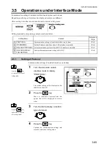
Confirmation of Communication Settings of RS-232C 

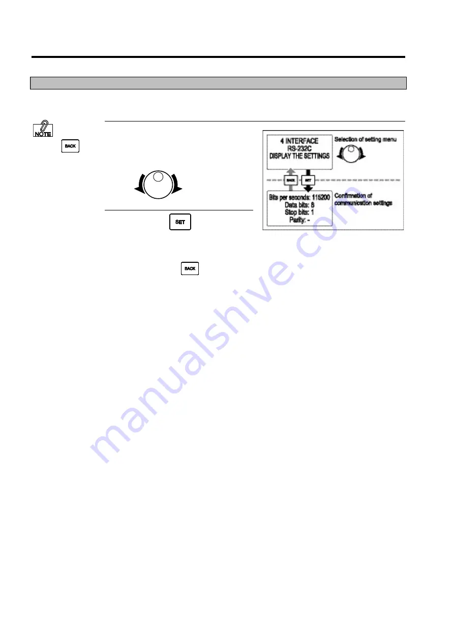
Below  is  an  explanation  of  the  procedures  for  confirming  the  communication  settings  in  the 
DipSW on the RS-232C interface board. 


1


Turn the dial under certain 

interface mode to display “RS-
232C DISPLAY THE SETTINGS”. 


2


Press the 

  key. 

Communication  settings  of  RS-232C  will 
be displayed.   
Confirm  the  communication  settings,  and 
please  press  the 


key  to  return  to 

selection of setting menu. 


Press  the 

  key 

to return to selection of 
setting mode. 

Содержание DURA SI600

Страница 1: ...THERMAL PRINTER INSTRUCTION MANUAL ...

Страница 2: ......

Страница 3: ...fonts and barcodes stored in the printer s memory For information on the commands refer to the DURA PRINTER SI600 Command Reference Manual on the accompanying CD for information on the interface required when issuing the commands refer to the DURA PRINTER SI600 Interface Manual It is necessary for proper printing that the operator familiarize himself herself with the commands before transmitting t...

Страница 4: ...r described in chapter 4 of the manual The copyright of this manual belongs to NITTO DENKO and NITTO DENKO keeps all rights Please do not duplicate or publicize any picture and or technical data without a previous written consent from NITTO DENKO If you have any question about this manual or you need more detailed information please go to the shop you purchased this product or our customer window ...

Страница 5: ...vant part s is are provided or repaired free of charge If the reason for inappropriateness is force majeure or product not delivered by us such circumstances are excluded If the reason for inappropriate is not clear solution to the problem shall be decided on the basis of agreement The company shall not be responsible for direct or indirect malfunctions or expenses incurred arising from use of the...

Страница 6: ...rning sheet pasted on the main part of this product Symbols Meaning Used under very dangerous situation when death or serious injury will be suffered if not avoided Used under dangerous situation when the machine device will be harmed or when minor injury or impairment at intermediate level will be suffered if not avoided Used to promote special attention and to convey emphasized information Used ...

Страница 7: ...function will also happen Please make sure that power source is AC 100V AC 240V If power source other than AC 100V AC 240V is used it will cause fire accident Please use the power cord provided in your package as accessory Please be sure that the main part terminals and other parts are not wet Parts carrying water will cause fire accident or malfunction Please do not unplug the power cord from soc...

Страница 8: ...ase your hands when it is still open in the midway or in the course of opening and or closing the cover will fall and will cause injury or malfunction Please be careful when opening and or closing the thermal head and or the press down area Placing your fingers and or hands in the area where the thermal head is tuned to move up and down will cause injury Moreover when opening the presser please co...

Страница 9: ...sudden shock Please do not disassemble it Disassembly will cause malfunction When transporting or moving the printer main part please remove label and thermal transfer ribbon Please do not use it in places where it is exposed to direct rays of the sun for a long time It will cause malfunction Please do not use it in places where temperature and humidity is high It will cause malfunction Please cho...

Страница 10: ...ting It not only causes malfunction but also will shorten service life of the printer For maintenance of the printer main part please wipe it with a soft dry cloth and neutral detergent Using of thinner and or others will cause deformation and or malfunction Please never use such substances ...

Страница 11: ...ge is divided into sections as follows Procedure layout 1 Describes cautionary remarks notes and reference pages on the left hand side of each page 2 Explains a particular procedure 3 Follow the operation procedures to show LCD messages or illustration ...

Страница 12: ...iew 1 2 Rear View 1 3 Operating Panel 1 4 1 2 Checking the Supplied Items Consumables Optional Units 1 5 1 2 1 Checking the Supplied Items 1 5 1 2 2 Consumables 1 5 1 2 3 Optional Unit 1 6 1 3 Installation Procedure 1 7 1 3 1 Connecting Cables 1 7 1 3 2 Turning on the Power 1 9 1 3 3 Turning off the Power 1 9 1 4 Installing the Thermal Transfer Ribbon 1 10 1 4 1 Installing the Thermal Transfer Rib...

Страница 13: ... 2 Selection of Setting Mode 3 5 3 1 3 Menu Flow of Setting Mode 3 6 3 2 Operations under LABEL SET Mode 3 7 3 2 1 Register New Print Configuration 3 8 3 2 2 Edit Print Configuration 3 9 Setting Menu for Print Configuration 3 10 3 2 3 Delete Print Configuration 3 11 3 3 Various Settings of Print Configuration 3 12 Using Label with Backing Paper 3 12 Using Label with I Mark 3 12 Using Continuous Pa...

Страница 14: ...tions under Advanced Mode 3 42 3 4 1 Confirmation of Printer Information 3 43 3 4 2 Setting of the Backfeed of Cutting 3 43 3 4 3 Setting of JIS Code 3 44 3 4 4 Setting of Zero Slash 3 45 3 4 5 Setting of Kanji Font 3 46 3 4 6 Adjustment of Print Darkness 3 47 3 4 7 Setting of Head Check 3 48 3 4 8 Setting of Auto Online 3 49 3 4 9 Setting of Auto Online Feed 3 50 3 4 10 Setting of Reprint on Erro...

Страница 15: ...n of Dump after Data Receiving 3 76 Printing of Printing Instruction 3 76 Saving of Printing Instruction 3 77 3 8 Operations under Sensor Check Mode 3 78 3 8 1 Confirmation of Gap Sensor I Mark Sensor 3 79 3 8 2 Confirmation of Head Up Sensor 3 80 3 8 3 Confirmation of Feed Roller Sensor 3 81 3 8 4 Confirmation of Ribbon Sensor 3 82 3 8 5 Confirmation of Dumper Sensor 3 83 3 8 6 Confirmation of He...

Страница 16: ...moval of CF Card Slot 5 4 5 3 Installing and Removing the Cutter Unit 5 5 5 3 1 Passing the Label Roll through Cutter Unit 5 7 5 4 Installing and Removing the Peeling Unit 5 8 5 4 1 Passing the Label Roll through the Dispenser Unit 5 10 Chapter 6 APPENDIX 6 1 6 1 Troubleshooting 6 2 6 2 Specifications 6 4 6 3 List of Default Settings 6 5 ...

Страница 17: ... 3 Operating Panel 1 4 1 2 Checking the Supplied Items Consumables Optional Units 1 5 1 2 1 Checking the Supplied Items 1 5 1 2 2 Consumables 1 5 1 2 3 Optional Unit 1 6 1 3 Installation Procedure 1 7 1 3 1 Connecting Cables 1 7 1 3 2 Turning on the Power 1 9 1 3 3 Turning off the Power 1 9 1 4 Installing the Thermal Transfer Ribbon 1 10 1 4 1 Installing the Thermal Transfer Ribbon 1 10 1 5 Instal...

Страница 18: ... Names and Functions of the Components The names of the parts together with their functions are explained Explanation in this manual is given using the following names Please remember these names and read next pages Front View ...

Страница 19: ...BEFORE OPERATION 1 3 Rear View ...

Страница 20: ...BEFORE OPERATION 1 4 Operating Panel ...

Страница 21: ...g please contact the shop where you bought this printer or our customer window The connecting cord used to connect this printer and your computer is not one of the accessories As the connecting cord is different based on the types of computer you use and this printer please prepare a connecting cord separately according to the User s Guide for your computer 1 2 2 Consumables Please use labels and ...

Страница 22: ... parts are supported by this printer If you bought any of these options please confirm that the option unit is loaded together with the package The Interface Unit does not function as print server So it cannot execute synchronous printing from multiple computers ...

Страница 23: ...ed by the interface installed to the printer and plug it in Any question about the optional units please contact the shop where you bought this printer or our customer window 4 The connection cord is installed to the cord clamp The front end of the cord clamp is inserted into the fixing part Pull the front end of the cord clamp and fix the connection cord E g When USB Board is installed Please set...

Страница 24: ... cord clamp Hold up the claw of the fixing part the pull out the cord clamp 5 Connect the Connecting Cord to your computer 6 Connect the Power Source Plug to the socket outlet Please never do octopus foot wiring for Power Cord It might cause fire ...

Страница 25: ...n the O side of the power button and power is turned OFF Power lamp goes out and the power source is disconnected Before turn the power OFF please confirm that printing operations are completed When remaining pages waiting to be printed is not 0 printing operations are not completed The printer is delivered with default language settings of Japanese If you want to change the language settings to b...

Страница 26: ...k Lever upwards and towards available directions The Thermal Head is lifted 4 Pull the knob that fastens the Ribbon Winder When opening the side cover please open it completely untill the top surface of the cover touches the printer main part If you release your hands when the cover is half open or in the midway of opening closing it the cover might fall and result in injury and or malfunction Whe...

Страница 27: ...the scale while moving the Ribbon Holder 7 Install the ribbon to the Ribbon Provider and let the tip of ribbon pass as shown in the picture 8 Keep the knob that fastens the Ribbon Winder pressed down Hold the tip of the ribbon plug in from the horizontal side and the ribbon can be set in smoothly Please let the ribbon run through the Sensor Guard Upper When the optional unit for rolling the paper ...

Страница 28: ... Ribbon will start winding by about 100 mm Please wind the ribbon tightly so that the ribbon does not slide off the Ribbon Winder Otherwise it might cause poor printing If you turn the ribbon feeder clockwise winding will be easier When the optional unit for rolling the paper roll ribbon is used please align the paper roll to the front end of the ribbon When the bonding force of the adhesive sheet...

Страница 29: ...r And the installation of Thermal Transfer Ribbon is completed If the Label Roll is still not installed please read 1 5 Installing the Label Roll on page 1 14 first and proceed with your operation 13 Press on the side of the Power Wwitch and power source is turned ON Power lamp lights up and the printer is started ...

Страница 30: ...is lifted 4 Keep the Dumper Arm released Hold and lift the Dumper Arm upwards to its maximum limit till it gives a clicking sound indicating that it is fastened When opening the side cover please open it completely untill the top surface of the cover touches the printer main part If you release your hands when the cover is half open or in the midway of opening closing it the cover might fall and r...

Страница 31: ... lock lever of Label Holder and remove the Label Holder from the Label holding Axis 8 Install the Label Roll onto the Label holding Axis decide its position with the Label Holder and fasten it Install Label Roll onto the Label holding Axis Install the Label Holder onto the Label holding Axis and push it in and fasten it with the lock lever so that there is no clearance from Label Roll Please do no...

Страница 32: ...e to the scale mark Set the label mat width to the number suitable for the mat width Please make sure that Label Roll passes in between the Sensor Guard Upper and Sensor Guard Lower Please set Centering Guide wide enough for Label to pass smoothly If label width is too narrow it will lead to trouble in feeding labels Moreover please do not turn the Fastening Nail more than 3 turns Hold the tip of ...

Страница 33: ...the label width When the reflection sensor is used Turn the lever to make the reflection sensor be located at the center of the I mark that is located at the back side of the label mat 14 Fasten the Presser Lower the Presser towards the lock till it gives a clicking sound indicating it is Fastened When locking the Presser please drag the label so that the label is tight without loosened space To f...

Страница 34: ...rds the lock Thermal Head is lowered 16 Close the Side Cover 17 Press on the side of the Power Switch and power source is turned ON Power lamp lights up and the printer is started When lowering the Thermal Head please drag the label so that the it is tight ...

Страница 35: ... width of Centering Guide After arranging the tip of Label Roll within the area shown in the picture and installing Label Roll press button till the tip of Label Roll is at the beginning position and stop For settings of Label Size 3 3 8 Setting of Label Size on pages 3 21 if Label pitch is set up in advance label can be printed online By pressing the button several times Label pitch can be saved ...

Страница 36: ...BEFORE OPERATION 1 20 ...

Страница 37: ...perating in Online Mode 2 4 Switching to Online Mode 2 4 2 2 2 Operating in Offline Mode 2 5 Switching to Offline Mode 2 6 Locating the Uptake Point of the Label Roll 2 6 Re Print a Label 2 6 Delete the Received Data 2 7 Change Print Configuration Label No 2 7 Adjust the Home Position of Label 2 8 Adjust Tear off Position Cutter Position Dispenser Position 2 9 Adjust Print Darkness 2 10 Stand Alon...

Страница 38: ...exterior parts Please wipe the dirty places with hardly squeezed soft cloth Dirtiness on the interior parts Wipe the dirty places on the interior parts with cloth For parts like thermal head and platen roller please remove dirty and label adhered thereto then wipe them with a cotton swab soaked with isopropyl alcohol Please read 4 1 Cleaning the Interior of the Printer on page 4 2 for details Conf...

Страница 39: ...inter is connected to computer and can receive data for printing offline refers to the status under which the printer is disconnected with computer and cannot receive data from the computer Please turn the printer Offline while setting up the printer on operating panel or doing any cleaning ...

Страница 40: ...amp lights up and the word ONLINE will be displayed on the LCD If there are labels to be printed printing will be restarted and the number of remaining labels to be printed will be displayed If the printer is under error status ERROR lamp lights up and error message is displayed on the LCD the printer is not online Please fix the problem causing the error and then switch the printer online The pri...

Страница 41: ...g Please read Change Print Configuration Label No on page P 2 7 for detailed operation Press the key to adjust the home position of label Please read Adjust the Home Position of Label on page P 2 8 for detailed operation Press the key to adjust operation position Please read Adjust Tear off Position Cutter Position Dispenser Position on page P 2 9 for detailed operation The contents for adjustment...

Страница 42: ...the beginning of label label pitch can be memorized 1 Press the key for a number of times The label can be fed until the beginning part is set ready for printing Re Print a Label Re print the label printed immediately previously 1 Press the key Print 1 piece of label previously printed If there is no previous printing of any label this operation is not effective If it is not stable please feed 3 4...

Страница 43: ... be displayed one by one 3 Press the key Return to the scene showing label No and the print configuration will be changed If you want to change the print configuration for different label size please refer to 1 5 Installing the Label Roll on page 1 14 for details Press the key and operation will be suspended This operation cannot be properly done if the printer is receiving data Please wait till t...

Страница 44: ... line is displayed in reverse video 2 Turn the dial and change the adjustment value Range for adjustment 50 000mm 50 000mm Adjustment interval 0 042mm 3 Press the key Confirm the adjustment value to return to previous scene and one piece of label will be test printed Confirm the printing position shown on the printed label If further adjustment is necessary do the operations again from step 1 Pres...

Страница 45: ...displayed on the LCD and the value line will be displayed in reverse video 2 Turn the dial and change the adjustment value Range for adjustment 50 000mm 50 000mm Adjustment interval 0 042mm 3 Press the key Confirm the adjustment value to return to previous scene and testing for the relevant printing mode will start Confirm the results of testing If further adjustment is necessary do the operations...

Страница 46: ...CD and the value line will be displayed in reverse video 2 Turn the dial to adjust print darkness Range for adjustment 100 100 3 Press the key Confirm the adjustment value to return to previous scene Press the key and operation will be suspended Print darkness can be adjusted by the unit of 1 But the resulted darkness with adjustment cannot be lower than 10 or higher than 100 If there is data wait...

Страница 47: ...source is disconnected 2 Insert the CF card in which printing instruction data is saved into the CF card slot on the rear of the printer 3 Press on the side of the Power Switch and power is turned ON Power lamp lights up and the printer is started under offline status 4 Press the key The printer is switch online It will read the printing instruction data in the CF card and start printing When prin...

Страница 48: ...BASIC OPERATIONS 2 12 ...

Страница 49: ...f Print Configuration 3 12 3 3 1 Printing Mode Settings 3 14 3 3 2 Setting of Cutter Position 3 15 3 3 3 Setting of Dispenser Position 3 16 3 3 4 Setting of Dispenser Time 3 17 3 3 5 Setting of Tear off Position 3 18 3 3 6 Setting of Home Position 3 19 3 3 7 Setting of Print Method 3 20 3 3 8 Setting of Label Size 3 21 3 3 9 Setting of Pitch Sensor 3 24 3 3 10 Adjustment of GAP Sensor I Mark Senso...

Страница 50: ...3 4 11 Setting of Printed Log 3 52 3 4 12 Setting of Stand Alone 3 53 3 4 13 Setting of Human Readable 3 54 3 4 14 Setting of External Signal 3 55 3 4 15 Confirmation of Total Counter 3 55 3 4 16 Confirmation of Head Counter 3 56 3 4 17 Confirmation of Platen Counter 3 56 3 4 18 Confirmation of Cutter Counter 3 56 3 4 19 Setting of Coordinates Adjustment 3 57 3 4 20 Default Setting 3 58 3 4 21 Adj...

Страница 51: ... Sensor I Mark Sensor 3 79 3 8 2 Confirmation of Head Up Sensor 3 80 3 8 3 Confirmation of Feed Roller Sensor 3 81 3 8 4 Confirmation of Ribbon Sensor 3 82 3 8 5 Confirmation of Dumper Sensor 3 83 3 8 6 Confirmation of Head Temperature 3 84 3 8 7 Confirmation of Inside Printer Temperature 3 84 3 8 8 Confirmation of Dispenser Sensor 3 85 3 8 9 Confirmation of External Signal Input 3 86 3 8 10 Confi...

Страница 52: ...NCED Settings about the basic operations of the printer like adjustment of LCD brightness and language change can be done INTERFACE Communication setting of installed interface board option can be done Depending on the type of interface the displayed contents are different TEST PRINT In order to confirm the conditions of printing test print of demo pattern printing and barcode printing can be done...

Страница 53: ...mode and the setting menu will be displayed Please read the following pages for operations under various setting menu LABEL SET Mode Please read 3 2 Operations under LABEL SET Mode on page 3 7 ADVANCED Mode Please read 3 4 Operations under Advanced Mode on page 3 42 INTERFACE Mode Please read 3 5 Operations under Interface Mode on page3 65 TEST PRINT Mode Please read 3 6 Operations under Test Prin...

Страница 54: ...SETUP PROCEDURE 3 6 3 1 3 Menu Flow of Setting Mode ...

Страница 55: ...ing etc can be done Management of print configuration is done via Label No and depending on the type and usage of label multiple numbers can be registered Label No can be registered from 01 to 100 for this printer and No 01 is registered as default setting After moving to LABEL SET mode turn the dial to select an option EDIT NEW DELETE of the print configuration for setting ...

Страница 56: ...tion of copy origin will be displayed 4 Press the key Decide the configuration for copy origin and move to selection of registered Label No the option line will be displayed in reverse video 5 Turn the dial to display the newly registered print configuration Label No 6 Press the key Register the new print configuration and return to selection of operation options Next please read 3 2 2 Edit Print ...

Страница 57: ...to display the edited print configuration Label No 4 Press the key Move to EDIT operation and a message of PRINTING MODE will be displayed in the third line of the setting menu on the LCD 5 Turn the dial to display the setting menu Please complete all operations on the entire setting menu that need editing For the specific options of setting menu for print configuration please read Setting Menu fo...

Страница 58: ...at is used for detecting label P 3 24 1 10 GAP1 SENSOR ADJUST Adjust the sensitivity of Gap1 Sensor P 3 25 1 11 GAP2 SENSOR ADJUST Adjust the sensitivity of Gap2 Sensor P 3 25 1 12 I MARK1 SENSOR ADJUST Adjust the sensitivity of I Mark1 Sensor P 3 25 1 13 I MARK2 SENSOR ADJUST Adjust the sensitivity of I Mark2 Sensor P 3 25 1 14 DETECT POSITION Set the Detect Position of label front rear P 3 28 1 ...

Страница 59: ...r deletion and the option line will be displayed in reverse video 3 Turn the dial to display the print configuration Label No for deletion 4 Press the key Move to the scene of confirming deletion 5 Turn the dial to display YES 6 Press the key Delete the print configuration and return to selection of operation options Press the key and return to selection of setting mode Press the key operation wil...

Страница 60: ...ia and the size under different printing modes The maximum label width available for setting is within the range of print size range of 109 0 mm For details about the available label width settings please read 6 2 Specifications on page 6 4 Using Label with Backing Paper If label with backing paper is used it is necessary to complete the settings below like printing position and size of the printe...

Страница 61: ...SETUP PROCEDURE 3 13 Using Continuous Paper If continuous paper is used it is necessary to complete the settings below like printing position and size of the printed label ...

Страница 62: ...sued continuously TEAR OFF After cutting off the issued media rewind back to printing position and go on with the next issuing operation CUTTER Cut off the issued media and move on to the next issuing operation It is enabled when the printer is installed with Cutter Unit option The maximum cutting capacity is 40 cut minute DISPENSER Peel off the issued media stand by for a certain period of time a...

Страница 63: ... under LABEL SET Edit mode The current preset value will be displayed in the fourth line on the LCD 2 Press the key Move to the operation of setting cutter position and the value line will be displayed in reverse video 3 Turn the dial to display the value for setting Range for Setting 50 000mm 50 000mm Adjustment Interval 0 042mm 4 Press the key Confirm the cutter position to return to the setting...

Страница 64: ...nu under LABEL SET Edit mode The current preset value will be displayed in the fourth line on the LCD 2 Press the key Move to the operation of setting dispenser position and the value line will be displayed in reverse video 3 Turn the dial to display the value for setting Range for Setting 50 000mm 50 000mm Adjustment Interval 0 042mm 4 Press the key Confirm the dispenser position to return to the...

Страница 65: ...isplay the DISPENSER TIME menu under LABEL SET Edit mode The current preset value will be displayed in the fourth line on the LCD 2 Press the key Move to the operation of setting Dispenser Time and the value line will be displayed in reverse video 3 Turn the dial to display the value for setting Range for Setting 0msec 5000msec 4 Press the key Confirm the Dispenser Time and return to selection of ...

Страница 66: ...ION menu under LABEL SET Edit mode The current preset value will be displayed in the fourth line on the LCD 2 Press the key Move to the operation of setting Tear off Position and the value line will be displayed in reverse video 3 Turn the dial to display the value for setting Range for Setting 15 000mm 15 000mm Adjustment Interval 0 042mm 4 Press the key Confirm the Tear off position to return to...

Страница 67: ...e LCD 2 Press the key Move to the operation of setting Home Position and the value line will be displayed in reverse video 3 Turn the dial to display the value for setting Range for Setting 50 000mm 50 000mm Adjustment Interval 0 042mm 4 Press the key Confirm the home position to return to the setting menu of operation selection and 1 piece of label will be printed for test Pressthe key and return...

Страница 68: ...the fourth line on the LCD 2 Press the key Move to selection of Print Method and the option line will be displayed in reverse video 3 Turn the dial to display print methods Print Method Content DIRECT Thermal paper is used as print media TRANSFER Transfer paper is used as print media 4 Press the key Confirm the print media and return to selection of setting menu Pressthe key and return to selectio...

Страница 69: ...LENGTH MEASURE Set whether to use the automatically measured value as the length of label when paper is fed Please read the under mentioned Enable Disable Auto Length Measure for operation procedures Set Label Width 1 Display WIDTH The current preset value will be displayed in the fourth line on the LCD 2 Press the key Move to the operation of setting label width and the width line will be display...

Страница 70: ... operation of setting label length and the length line will be displayed in reverse video 3 Turn the dial to display label length Range for Setting 1 0mm 400 0mm 4 Press the key Confirm the label length set and return to selection of options for setting Press the key to return to selection of items for setting Adjustment can be done by the unit of 0 1 mm ...

Страница 71: ...ion of setting auto length measure and the length line will be displayed in reverse video 3 Turn the dial to display ENABLE DISABLE Auto Length Measure Content DISABLE Manually input a value as the length of label and auto length measure does not take effects ENABLE Set whether to use the Auto Length Measure value automatically measured by pitch sensor label sensor as label length 4 Press the key ...

Страница 72: ...re used with the following calculation equation If the label pitch can fit in nowhere please use Gap1 sensor If the label pitch can fit in both either an error or a Skip occurs Please select a label pitch that does not fall in this range I MARK1 Selected when label is detected according to the reflectivity of label Normally I Mark1 sensor is used Media Supported Label with I Mark Please use the la...

Страница 73: ... value light quantity on the left threshold value on the right will be displayed 2 Press the key Move to selection of adjustment options and the option line will be displayed in reverse video 3 Turn the dial to display a random adjustment option Pitch Sensor Content AUTO Automatically adjust pitch sensor Please read under mentioned Auto Adjustment of Pitch Sensor for detailed operational procedure...

Страница 74: ...he key Confirm the content of adjustment and return to selection of adjustment options Please remember to lock the head and the presser and then close the side cover Press the key and return to selection of adjustment options Press the key and return to selection of adjustment options without confirming the result of adjustment When opening the side cover please open it completely untill the top s...

Страница 75: ...entioned Adjustment of Threshold Value for detailed operational procedures Adjustment of Light Quantity 1 Display LIGHT QUANTITY 2 Set the mat of the label on the sensor then push Move to the operation of light quantity adjustment and the Light Quantity line will be displayed in reverse video 3 Turn the dial to adjust the light volume Adjust the light volume to set the output to the following valu...

Страница 76: ...preset value will be displayed in the fourth line on the LCD 2 Press the key Move to selection of DETECT POSITION options and the option line will be displayed in reverse video 3 Turn the dial to display a random detect position Detect Position Content FRONT Set the front of label as detect position REAR Set the rear of label as detect position 4 Press the key Confirm the detect position and retur...

Страница 77: ...e displayed in the fourth line on the LCD 2 Press the key Move to the operation of setting print speed and the value line will be displayed in reverse video 3 Turn the dial to display a random print speed Range for Setting 25mm s 150mm s 4 Press the key Confirm the print speed and return to selection of setting menu Pressthe key and return to selection of a setting menu Print speed can be adjusted...

Страница 78: ...The current preset value will be displayed in the fourth line on the LCD 2 Press the key Move to the operation of setting print darkness and the value line will be displayed in reverse video 3 Turn the dial to display a random print darkness Range for Setting 10 100 4 Press the key Confirm the print darkness and return to selection of setting menu Pressthe key and return to selection of a setting ...

Страница 79: ... of change in relation to this percentage 1 Display the PLATEN ADJUST menu under LABEL SET Edit mode The current preset value will be displayed in the fourth line on the LCD 2 Press the key Move to adjustment of Platen Roller and the option line will be displayed in reverse video 3 Turn the dial to display adjustment value Range for Setting 90 0 110 0 4 Press the key Confirm the adjustment value f...

Страница 80: ...layed in reverse video 3 Turn the dial to display the print quality In case print speed is below 50 mm s please set the value to match standard 75mm s In case of over 75 mm s please set the value appropriately to either of standard high grade 1 or high grade 2 Depending on the type of label or pulse division settings the configuration of QR code printing setting may change 4 Press the key Confirm ...

Страница 81: ...play the CONTINUOUS PAPER menu under LABEL SET Edit mode 2 Press the key Move to selection of setting options and the current preset value will be displayed in the fourth line on the LCD 3 Turn the dial to display the items for setting If DISABLE is displayed in the fourth line on the LCD only option Continuous Paper can be displayed selected Option for Setting Content CONTINUOUS PAPER Set whether...

Страница 82: ...tent DISABLE Set not to use continuous paper for current print configuration ENABLE Set to use continuous paper for current print configuration 4 Press the key Confirm the selection of enabling disabling continuous paper and return to selection of setting options When DISABLE is selected setting of continuous paper is finished here and please press the key to return to selection of setting menu Wh...

Страница 83: ...ABEL SET Edit mode 2 Press the key Move to selection of setting options and the current preset value will be displayed in the fourth line on the LCD 3 Turn the dial to display the options for setting Options for Setting Content WIDTH Set the adjustment value for the origin position of coordinates to be horizontally shifted according to command Please read Setting of Printing Position Width for det...

Страница 84: ...idth and return to selection of options for setting Setting of Printing Position Length 1 Display LENGTH The current preset value will be displayed in the fourth line on the LCD 2 Press the key Move to the operation of setting length adjustment and the option line will be displayed in reverse video 3 Turn the dial to display a random value Range for Setting 400 000mm 400 000mm Adjustment Interval ...

Страница 85: ...reset value will be displayed in the fourth line on the LCD 2 Press the key Move to selection of designated print configuration options and the option line will be displayed in reverse video 3 Turn the dial to display ENABLE DISABLE Define the printing condition Content DISABLE Apply the settings in the printer as print configuration ENABLE Apply the settings based on command as print configuratio...

Страница 86: ...urrent preset value will be displayed in the fourth line on the LCD 2 Press the key Move to the operation of setting tear off time and the value line will be displayed in reverse video 3 Turn the dial to display the value for setting Range for Setting 0msec 5000msec 4 Press the key Confirm the tear off time and return to selection of setting menu Pressthe key and return to selection of a setting m...

Страница 87: ...rinting Content DISABLE Heat the thermal head all together The option is selected if both the compatibility between thermal transfer ribbon and thermal transfer paper as well as the transferring effect are good ENABLE Heat the thermal head in separated parts The option is selected if the compatibility between thermal transfer ribbon and thermal transfer paper is good while transferring effect is n...

Страница 88: ...g setting the label and ribbon combination the selected row will be highlighted 3 When you turn the dial the relevant number will be shown Range for Setting 0 99 The Combination Number of Label and Ribbon Label Ribbon 0 General combination 1 P251H H 2 P251H H20 3 PT50NS H 4 PT50NS H20 5 10PN 10PN 6 99 General combination If the printing speed is over 75mm s it always uses the general combination f...

Страница 89: ...der LABEL SET Edit mode The current preset value will be displayed in the fourth line on the LCD 2 Press the key Move to selection of label skip and the option line will be displayed in reverse video 3 Turn the dial to display ENABLE DISABLE Label Skip Content DISABLE Error occurs when label is peeled off ENABLE Even if label is peeled off error does not occur and printing continues with the next ...

Страница 90: ... to allow stand alone application depending on CF card It is enabled only when the printer is installed with CF card slot option When stand alone printing is enabled there will be no communication with computer P 3 53 13 HUMANREADABLE Set the handwriting style of the readable text of JAN to be printed below barcode P 3 54 14 EXTERNAL SIGNAL Set whether to allow input output of external signal It i...

Страница 91: ... when Cutter Unit option is installed 1 Under advanced mode turn the dial to display BACKFEED OF CUTTING The current setting will be displayed in the third line on the LCD 2 Press the key Move to selection of backfeeding operations and the option line will be displayed in reverse video 3 Turn the dial to display a random setting option Setting Content BEFORE PRINT Bacefeeding starts from cutter po...

Страница 92: ...n the third line on the LCD 2 Press the key Move to selection of JIS code and the option line will be displayed in reverse video 3 Turn the dial to display a random coding system Setting Content JIS JIS code SJIS SJIS code 4 Press the key Confirm the settings of JIS code and return to selection of setting menu Press the key to return to selection of setting mode Press the key to return to selectio...

Страница 93: ...y Move to selection of zero slash and the option line will be displayed in reverse video 3 Turn the dial to display a random print method Setting Content Print Example NO Print Zero without slash YES Print Zero with a slash 4 Press the key Confirm the settings of zero slash and return to selection of setting menu Press the key to return to selection of setting mode Pressthe key and return to selec...

Страница 94: ... the LCD 2 Press the key Move to selection of kanji font and the option line will be displayed in reverse video 3 Turn the dial to display a random type of font Setting Content GOTHIC Print the text in Gothic font MINCHO Print the text in Mincho font 4 Press the key Confirm the settings of kanji font and return to selection of setting menu Press the key to return to selection of setting mode Press...

Страница 95: ...nt darkness classifications 3 Turn the dial to display a random classification 4 Press the key Move to the operation of setting print darkness and the option line will be displayed in reverse video 5 Turn the dial to display a random value Range for Setting 10 100 6 Press the key Confirm the selected classification of print darkness and return to selection of print darkness classifications Press t...

Страница 96: ...e to the operation of setting head check and the option line will be displayed in reverse video 3 Turn the dial to display a random setting option Setting Content DISABLE No head check ENABLE Start head check when the printer stands by 4 Press the key Confirm the settings of Head Check and return to selection of setting menu Press the key to return to selection of setting mode Pressthe key and ret...

Страница 97: ...2 Press the key Move to the operation of setting start mode and the option line will be displayed in reverse video 3 Turn the dial to display a random setting option Setting Content NO Start the printer offline YES Start the printer online 4 Press the key Confirm the start mode and return to selection of setting menu Press the key to return to selection of setting mode Pressthe key and return to s...

Страница 98: ... Move to the operation of setting Auto Online Feed and the option line will be displayed in reverse video 3 Turn the dial to display a random setting option Setting Content NO No paper feeding at start YES Feed 1 page of label at start 4 Press the key Confirm the settings of Auto Online Feed and return to selection of setting menu Press the key to return to selection of setting mode Pressthe key a...

Страница 99: ... and the option line will be displayed in reverse video 3 Turn the dial to display a random setting option Setting Content NO If error occurs do not reprint the label that has been printed right before the error The printed label is counted as a properly printed one YES If error occurs reprint the label that has been printed right before the error 4 Press the key Confirm the settings of reprint on...

Страница 100: ... be displayed in the third line on the LCD 2 Press the key Move to selection of printed log and the option line will be displayed in reverse video 3 Turn the dial to display a random setting option Setting Content DISABLE Disable the function of printed log ENABLE Enable the function of printed log 4 Press the key Confirm the settings of printed log and return to selection of setting menu Press th...

Страница 101: ... STAND ALONE The current setting will be displayed in the third line on the LCD 2 Press the key Move to selection of stand alone and the option line will be displayed in reverse video 3 Turn the dial to display a random setting option Setting Content DISABLE The printer cannot be used as stand alone printer ENABLE The printer is set as stand alone printer and cannot receive print instructions from...

Страница 102: ...n the third line on the LCD 2 Press the key Move to the operation of setting text style and the option line will be displayed in reverse video 3 Turn the dial to display a random handwriting style Option Print Example OCR B OCR A Small 4 Press the key Confirm the settings of handwriting style and return to selection of setting menu Press the key to return to selection of setting mode Pressthe key ...

Страница 103: ... display a random setting option Setting Content DISABLE External signal cannot be input or output ENABLE External signal can be input or output 4 Press the key Confirm the settings of external signal and return to selection of setting menu 3 4 15 Confirmation of Total Counter Confirm the total counter of Platen Roller based on its rotation since delivery 1 Under advanced mode turn the dial to dis...

Страница 104: ...ode turn the dial to display PLATEN COUNTER Platen counter is displayed in the third line on the LCD 3 4 18 Confirmation of Cutter Counter Confirm cutter counter of Cutter Unit here It is enabled only when Cutter Unit option is installed 1 Under advanced mode turn the dial to display CUTTER COUNTER Cutter Counter is displayed in the third line on the LCD Press the key to return to selection of set...

Страница 105: ...d in reverse video 3 Turn the dial to display a random option for adjustment Setting Content NORMAL No adjustment of printing position ADJUSTMENT When the label width designated in computer is smaller than the printing width actually available adjust half the difference by moving towards the right side ADJUSTMENT When the label width designated in computer is larger than the printing width actuall...

Страница 106: ...to display DEFAULT SETTING 2 Press the key Confirming message of initialization is displayed 3 Turn the dial to display YES 4 Press the key Initialization starts After the process is finished return to selection of setting menu Press the key to return to selection of setting mode Pressthe key and return to selection of a setting menu If NO is displayed and selected the process of initialization wi...

Страница 107: ...e third line on the LCD 2 Press the key Move to the operation of adjusting LCD brightness and the value line will be displayed in reverse video 3 Turn the dial while looking at the LCD to display a random brightness Range for Setting 0 254 4 Press the key Confirm the LCD brightness and return to selection of setting menu Press the key to return to selection of setting mode Pressthe key and return ...

Страница 108: ...end label processing operations and the option line will be displayed in reverse video 3 Turn the dial to display a random setting option Setting Content DISABLE Error occurs to the last label and it is regarded as a label to be disposed of ENABLE Error does not occur to the last label and effective printing of the last page of label can be properly finished 4 Press the key Confirm the settings of...

Страница 109: ...urrent setting will be displayed in the third line on the LCD 2 Press the key Move to selection of buzzer sound operations and the option line will be displayed in reverse video 3 Turn the dial to display a random setting option Setting Content DISABLE Buzzer sound is disabled ENABLE Buzzer sound rings when abnormality occurs 4 Press the key Confirm the settings of buzzer sound and return to selec...

Страница 110: ... option line will be displayed in reverse video 3 Turn the dial to display a random language option Setting Content Display in Japanese ENGLISH Display in English 4 Press the key Confirm your choice of display language and return to selection of setting menu After confirming the display language the setting soon is applied Please read 3 1 3 Menu Flow of Setting Mode on page 3 6 for details about t...

Страница 111: ...n the dial to display a random value and press the key to display the next digit Range for Setting 0 99999999 4 Press the key Confirm registration of the password and return to selection of setting menu Press the key to return to selection of setting mode After inputing the number press the key and cursor will move to the previous digit When cursor moves to the headmost press the key and return to...

Страница 112: ...nd the option line will be displayed in reverse video 3 Turn the dial to display ENABLE DISABLE Key Lock Content DISABLE All of the keys can be operated ENABLE The registered password becomes effective If the password does not match correctly keys cannot be operated if password matches correctly all the keys can be operated 4 Press the key Confirm the key lock setting and return to selection of se...

Страница 113: ... PROTOCOL Set communication protocol when RS 232C interface is installed P 3 67 4 RS 232C DISPLAY THE SETTING Confirm the communication setting of RS 232C P 3 68 3 5 1 Setting of Protocol Communication settings of installed interface can be done 1 Turn the dial under certain interface mode to display PROTOCOL The current setting will be displayed in the third line on the LCD 2 Press the key Move t...

Страница 114: ...s are set current value of subnet mask will be displayed 5 Press the key Move to the operation of setting subnet mask and the first input area is displayed in reverse video 6 Turn the dial to display a random subnet mask and press the key or the key to switch to the next input area When all of the input areas for subnet mask are set the current preset value of gateway will be displayed Press the k...

Страница 115: ...tain interface mode to display RS 232C PROTOCOL The current setting will be displayed in the fourth line on the LCD 2 Press the key Move to selection of protocol and the option line will be displayed in reverse video 3 Turn the dial to display a random type of protocol When STATUS is selected from the list of protocols the protocol that has been selected in menu 1 PROTOCOL Please refer to 3 5 1 Se...

Страница 116: ...ttings in the DipSW on the RS 232C interface board 1 Turn the dial under certain interface mode to display RS 232C DISPLAY THE SETTINGS 2 Press the key Communication settings of RS 232C will be displayed Confirm the communication settings and please press the key to return to selection of setting menu Press the key to return to selection of setting mode ...

Страница 117: ...e P 3 70 3 HEAD CHECK Finish head check and print out the results of head check P 3 71 4 FONT LIST Test print the fonts supported by this printer P 3 72 5 CHECK PATTERN Print out the check pattern P 3 72 6 CONTET OF CF CARD Print out the contents saved in CF card Effective printing can be done only when CF card slot option is installed P 3 73 3 6 1 Printing of Settings Print out the contents of se...

Страница 118: ...der Test Print mode turn the dial to display BARCODE 2 Press the key Print the barcode and return to selection of setting menu Print Example Press the key to return to selection of setting mode Printing cannot be suspended In case errors like end label occur during printing press the key to start reprinting ...

Страница 119: ...thermal head in reference to 4 2 Replacing the Thermal Head on page 4 8 Checking Item Content LCD Message Print Damage in dot number DAMAGE Show the damage of head in dot number COUNTER Show the head counter Average Resistance MEASURE Show the average resistance of thermal head Head Rank RANK Show the resistance rank of thermal head 4 Press the key Return to selection of setting menu Print Example...

Страница 120: ...n 1 Under Test Print mode turn the dial to display CHECK PATTERN 2 Press the key Print the check pattern and return to selection of setting menu Print Example Press the key to return to selection of setting mode Printing cannot be suspended Press the key to return to selection of setting mode Printing cannot be suspended In case errors like end label occur during printing press the key to start re...

Страница 121: ...ion is installed 1 Under Test Print mode turn the dial to display CONTET OF CF CARD 2 Press the key Print the data saved in CF card and return to selection of setting menu Print Example Press the key to return to selection of setting mode Printing cannot be suspended In case errors like end label occur during printing press the key to start reprinting ...

Страница 122: ...ump Receive printing instruction from computer and print the contents or save the contents into CF card In case of printing out onto the label please refer to Printing of Printing Instruction and in case of saving into CF card please refer to Saving of Printing Instruction Printing of Printing Instruction 1 Under dump mode turn the dial to display ONLINE DUMP 2 Press the key Move to selection of o...

Страница 123: ...he key Turn the printer online to receive printing instruction from computer and save the data into CF card while at the same time regular printing operations continue Online dump cannot be canceled untill power source is disconnected Before disconnecting the power source please be certain to press the key so as to temporarily stop the printer Press the key to return to selection of setting mode P...

Страница 124: ...nto CF card please refer to Saving of Printing Instruction Printing of Printing Instruction 1 Under dump mode turn the dial to display RECEIVED DATA DUMP 2 Press the key Move to selection of output destination 3 Turn the dial to display LABEL 4 Press the key Print out the contents for printing When printing is finished return to selection of setting menu Press the key to return to selection of set...

Страница 125: ...Press the key Move to selection of output destination 3 Turn the dial to display CF CARD 4 Press the key Save the contents for printing into CF card When saving is finished return to selection of setting menu Press the key to return to selection of setting mode Press the key and return to selection of a setting menu ...

Страница 126: ...peration to see whether ribbon sensor is properly functioning P 3 82 8 DUMPER SENSOR Please lower the dumper arm first and check the operation to see whether the dumper sensor is properly functioning P 3 83 9 HEAD TEMPERATURE Check whether the temperature of thermal head is correctly displayed P 3 84 10 PRINTER TEMPERATURE Check whether the temperature inside the printer is correctly displayed P 3...

Страница 127: ...s an example for explanation 1 Under Sensor Check mode turn the dial to display GAP1 SENSOR 2 Press the key Feed 1 page of label to check the operation as to whether label can be detected or not After checking results will be displayed on the LCD Results Content OK Label detection successful Sensor works properly NG Label detection failure There might be some abnormality 3 Press the key Return to ...

Страница 128: ...nd buzzer sound Below is indication of proper operations Status LCD Message Buzzer Sound Free UP A Give beeping sound Locked DOWN A Give beeping sound 5 Press the key Return to selection of setting menu Please turn the head lock lever into locked status and close the side cover Press the key to return to selection of setting mode When opening the side cover please open it completely untill the top...

Страница 129: ...low is indication of proper operations Status LCD MESSAGE Buzzer Sound Free UP B Give beeping sound Locked DOWN B Give beeping sound 5 Press the key Return to selection of setting menu Please turn the presser into locked status and close the side cover Press the key to return to selection of setting mode When opening the side cover please open it completely untill the top surface of the cover touc...

Страница 130: ...e ribbon feeder from between the feed side and return side and confirm the LCD message as well as buzzer sound Below is indication of proper operations Status LCD MESSAGE Buzzer Sound Feed Side ON Give beeping sound Return Side OFF Give beeping sound 5 Press the key Return to selection of setting menu Close the side cover Press the key to return to selection of setting mode When opening the side c...

Страница 131: ...e dumper arm between free and locked status and confirm the message on the LCD and buzzer sound Below is indication of proper operations Status LCD MESSAGE Buzzer Sound Free UP C Give beeping sound Locked DOWN C Give beeping sound 5 Press the key Return to selection of setting menu Please turn the dumper arm into locked status and close the side cover Press the key to return to selection of settin...

Страница 132: ...ress the key Return to selection of setting menu 3 8 7 Confirmation of Inside Printer Temperature Check whether the temperature inside the printer is correctly displayed 1 Under sensor check mode turn the dial to display PRINTER TEMPERATURE 2 Press the key Printer temperature will be displayed in the third line on the LCD 3 Press the key Return to selection of setting menu Press the key to return ...

Страница 133: ...it option is installed Even buzzer sound is disabled under advanced mode the buzzer still rings for confirmation 1 Under sensor check mode turn the dial to display DISPENSER SENSOR 2 Press the key Move to checking of dispenser sensor operations 3 Insert label in between the light emitting and light sensing devices of dispenser sensor and confirm the operations of the sensor Confirm the message on ...

Страница 134: ...eceived Checking is only necessary when input terminal option for external signal is installed 1 Under sensor check mode turn the dial to display EXTERNAL SIGNAL INPUT CHECK 2 Press the key Status of the input signal will be displayed on the LCD Result Content ON Signal ON OFF Signal OFF 3 Press the key Return to selection of setting menu Press the key to return to selection of setting mode ...

Страница 135: ...OUTPUT CHECK 2 Press the key Move to setting of BUSY 3 Turn the dial to display ON OFF Setting Content ON Turn ON OFF Turn OFF When switching between ON OFF the external signal changes too Therefore please confirm the output signal in the connected external equipment 4 Press the key Move to setting of ONLINE 5 Repeat step 3 and step 4 and confirm the 4 types of output signal namely BUSY ONLINE END...

Страница 136: ...Open the side cover 4 Insert the white paper in between the light emitting and light sensing devices of end tape sensor and confirm the operations of the sensor Confirm the message on LCD Below table shows the operations under normal condition White Paper Status LCD MESSAGE Passed OFF Pulled out ON 5 Press the key Return to selection of setting menu Press the key to return to selection of setting ...

Страница 137: ...rom computer and the program can be rewritten P 3 89 2 CF CARD Program data can be received from CF card and the program can be rewritten Operations are enabled only when CF card slot option is installed P 3 90 3 9 1 Online Version Up Program data can be received from computer and the program can be 1 Under version up mode turn the dial to display ONLINE 2 Press the key Communication with computer...

Страница 138: ... slot option is installed 1 Under version up mode turn the dial to display CF CARD 2 Press the key Search the program in CF card and rewrite the program When rewriting is finished the printer will be restarted If there is no program in CF card or if there is no CF card inserted in the slot a message will be displayed Press the key to return to selection of setting mode ...

Страница 139: ...CE 4 1 Chapter 4 MAINTENANCE This chapter explains how to clean and replace the various parts 4 1 Cleaning the Interior of the Printer 4 2 4 2 Replacing the Thermal Head 4 8 4 3 Replacement of Platen Roller 4 12 ...

Страница 140: ...ed 4 Remove the thermal transfer ribbon When opening the side cover please open it completely untill the top surface of the cover touches the printer main part If you release your hands when the cover is half open or in the midway of opening closing it the cover might fall and result in injury and or malfunction For details about how to remove the thermal ribbon please read the steps 4 to 5 of 1 4...

Страница 141: ...d remove the dumper roller 7 Release the Presser Push the Presser Release Lever and the Presser is released Lift the Presser and fasten it with Magnet 8 Remove the label holder from label holding axis and then remove the label roll Release the lock lever of Label Holder and remove the Label Holder from the Label holding Axis Please confirm that after the Presser is released it is well fastened wit...

Страница 142: ...l alcohol to wipe the platen roller and the ribbon roller gently 11 Remove the Sensor Guard upper and lower and wipe off the dirtiness on the surface Remove the Sensor Guard upper and turn the fastening bolt of the Sensor Guard lower to remove it After cleaning install the upper and lower Sensor Guards as it was previously installed ...

Страница 143: ... undersurface of the printer and install the Centering Guide unit as it was previously installed Insert the projection part of the Centering Guide unit into the grooved hole on the inner side of the frame and then tighten the fastening bolt 15 Install the label roll and the Thermal Transfer Ribbon For details of how to install the Thermal Transfer Ribbon and Label Roll please read the steps 6 to 1...

Страница 144: ... 17 Lower the Dumper Arm Hold and lift the Dumper Arm upward to its maximum limit till it gives a clicking sound indicating it is released and lower the Dumper Arm without releasing your hands 18 Lower the Head Lock Lever towards the lock Thermal Head is lowered 19 Close the Side Cover When releasing the Dumper Arm please do not pull it down forcibly ...

Страница 145: ...lter Remove the air filter and wash it with water after it is completely dry install it as it was previously installed 21 Press on the side of the Power Switch and power source is turned ON Power lamp lights up and the printer is started ...

Страница 146: ...l Head is lifted 4 Remove the thermal transfer ribbon When opening the side cover please open it completely untill the top surface of the cover touches the printer main part If you release your hands when the cover is half open or in the midway of opening closing it the cover might fall and result in injury and or malfunction If heat sensitive label is used please proceed with the following steps ...

Страница 147: ...l the new Thermal Head Please do not drag the Harness forcibly Please install the Harness to its previous position where it does not touches the Thermal Transfer Ribbon Please do not touch the heat generating part of the Thermal Head with your bare hands It will cause bad quality in printing Please do not touch the heat generating part of the Thermal Head with your bare hands It will cause bad qua...

Страница 148: ...the fastening lever of the Thermal Head 9 Move the Thermal Head forward and backward Please move the part forward and backward until it gives a short snapping sound to confirm that the part can move smoothly 10 Install the Thermal Transfer Ribbon Please read the steps 6 to 10 of 1 4 1 Installing the Thermal Transfer Ribbon on page 1 10 for details of how to install the Thermal Transfer Ribbon ...

Страница 149: ...11 11 Lower the Head Lock Lever towards the lock Thermal Head is lowered 12 Close the Side Cover 13 Press on the side of the Power Switch and power source is turned ON Power lamp lights up and the printer is started ...

Страница 150: ...side cover please open it completely untill the top surface of the cover touches the printer main part If you release your hands when the cover is half open or in the midway of opening closing it the cover might fall and result in injury and or malfunction For details about how to remove the thermal ribbon please read the steps 4 to 5 of 1 4 1 Installing the Thermal Transfer Ribbon on page 1 10 If...

Страница 151: ...en the fastening nail of roller bracket with a plus driver and remove the roller bracket 8 Pull out Platen Roller On the Platen Roller for replacement there shall be fastening nail for Platen Roller already attached When pulling out the Platen Roller please remove the fastening nail together with the Platen Roller Please be careful not to let your hand or fingers hurt by the jag surrounding the Pl...

Страница 152: ...ller bracket fastening nail unfastened in Step 7 Please set the protruding part of the roller bracket into the hole and fasten it 11 Push in the Platen Roller towards roller bracket so that the rotation base well fits the hole of roller bracket 12 Tighten the fastening nail of Platen Roller ...

Страница 153: ...rection until it gives a short snapping sound and the presser is fastened 15 Lower the Head Lock Lever towards the lock Thermal Head is lowered 16 Close the Side Cover For details about how to install the Thermal Transfer Ribbon please read the steps 6 to 10 of 1 4 1 Installing the Thermal Transfer Ribbon on page 1 10 ...

Страница 154: ...MAINTENANCE 4 16 17 Press on the side of the Power Switch and power source is turned ON Power lamp lights up and the printer is started ...

Страница 155: ... and remove the optional units 5 1 Installing and Removing the Interface 5 2 5 2 Installation and Removal of CF Card Slot 5 4 5 3 Installing and Removing the Cutter Unit 5 5 5 3 1 Passing the Label Roll through Cutter Unit 5 7 5 4 Installing and Removing the Peeling Unit 5 8 5 4 1 Passing the Label Roll through the Dispenser Unit 5 10 ...

Страница 156: ...er is turned OFF Power Lamp goes out and the power source is disconnected 2 Pull out the power source plug from the socket outlet 3 On the rear of the printer unfasten 1 bolt and remove the Interface Cover No 1 Please be sure that the power source plug is pulled out from the socket outlet Otherwise it might cause injury and or malfunction The unfastened bolt will be used to install the option inte...

Страница 157: ...communication For details of how to set up the interface please read 3 5 Operations under Interface Mode on page 3 65 Removing Procedures Please complete the operation by following the reversed order of installation procedures starting from step 4 Please be sure that the interface board is inserted If the insertion is loose the printer might not be able to recognize the interface ...

Страница 158: ...F Card Slot along the rail and fasten it with the accessory bolt and the unfastened bolt in step 3 Removing Procedures Please complete the operation by following the reversed order of installation procedures starting from step 4 Please be sure that the power source plug is pulled out from the socket outlet Otherwise it might cause injury and or malfunction The unfastened bolt will be used to insta...

Страница 159: ...ections The Thermal Head is lifted Before turn the power OFF please confirm that printing operations are completed When remaining pages waiting to be printed is not 0 printing operations are not completed Please be sure that the power source plug is pulled out from the socket outlet Otherwise it might cause injury and or malfunction When opening the side cover please open it completely untill the ...

Страница 160: ...THE OPTIONAL UNIT 5 6 5 Unfasten 2 bolts and remove the Front Cover 6 Unfasten 1 bolt and remove the interior cover 7 Link the connector of the Cutter Unit 8 Insert the cut under the Cutter Unit into the groove of the printer ...

Страница 161: ...arting from step 9 Next please read 1 5 Installing the Label Roll on page 1 14 and install the Label Roll After passing the front of label roll through the Thermal Head please follow the procedures below to pass the front of label roll through the Cutter Unit 5 3 1 Passing the Label Roll through Cutter Unit 1 Raise the Cutter Unit and pass the label into the Cutter Unit 2 Close the Cutter Unit Pus...

Страница 162: ...irections The Thermal Head is lifted Before turn the power OFF please confirm that printing operations are completed When remaining pages waiting to be printed is not 0 printing operations are not completed Please be sure that the power source plug is pulled out from the socket outlet Otherwise it might cause injury and or malfunction When opening the side cover please open it completely untill th...

Страница 163: ...nfasten 1 bolt and remove the interior cover 7 Link the connector of the Dispenser Unit 8 Press the to open the Dispenser Unit and hitch the hooks two places onto the printer The unfastened bolt A will be used to install the option interface board Therefore please be careful not to throw it away ...

Страница 164: ...ter and install it with the bolt A unfastened in step 5 Removing Procedures Please complete the operation by following the reversed order of installation procedures starting from step 10 Next please read 1 5 Installing the Label Roll on page 1 14 and install the Label Roll After passing the front of label roll through the Thermal Head please follow the procedures below to pass the front of label r...

Страница 165: ...h the peel off unit 3 Close the Dispenser Unit Push the Dispenser Unit towards the inner side if it gives a short snapping sound it is fastened Please keep the label in full tension and then set it Otherwise if the label mat gets loose the label cannot be normally peeled off ...

Страница 166: ...INSTALLING AND REMOVING THE OPTIONAL UNIT 5 12 ...

Страница 167: ...INSTALLING AND REMOVING THE OPTIONAL UNIT 5 13 ...

Страница 168: ...plain what to do when error message is displayed or other problems occur In addition tables of specifications and list of default settings are also provided 6 1 Troubleshooting 6 2 6 2 Specifications 6 4 6 3 List of Default Settings 6 5 ...

Страница 169: ...ibbon End 1 There is no ribbon 2 Ribbon runs out 1 Please properly set ribbon and press the key 2 Please clean the ribbon transportation route Cutter Error 1 Label and or media jam occurs in Cutter 2 The blade of Cutter is not properly restored to the designated position 1 Please turn off power 2 Please clean the Cutter 3 Turn on power again Head Damaged There is damage of head dot Please replace ...

Страница 170: ...ermal head TYPE OF HEAD IS DIFFERENT PLEASE EXCHANGE THE HEAD The type of the installed head does not match such as different head density Please install the right type of thermal head TYPE OF MACHINE IS DIFFERENT PLEASE ANY KEY TO CHANGE TO UPDATE MODE Firmware does not match the printer type Please update the version so that the firmware matches the printer type If the problem cannot be solved i...

Страница 171: ...ot X22 24 24 dot X23 48 48 Bold dot X24 48 48 Regular dot Kanji Font 16 16 dot JIS Standard No 1 and No 2 Mincho Gothic 22 22 dot JIS Standard No 1 and No 2 Mincho Gothic 24 24 dot JIS Standard No 1 and No 2 Mincho Gothic 32 32 dot JIS Standard No 1 and No 2 Mincho Gothic 40 40 dot JIS Standard No 1 and No 2 Mincho Gothic Outline Font Gothic Letters Numbers Symbols and Katakana OCR A 44 66 dot OCR...

Страница 172: ...0 GAP2 sensor adjust Light quantity Threshold 140 I mark 1 sensor adjust Light quantity Threshold 100 I mark 2 sensor adjust Light quantity Threshold 100 Detect position Front Print speed 50 mm s Print darkness 95 Platen adjust 100 0 QR code print Standard Continuous paper Continuous paper specifications Disable Gap between pages 0 0 mm Printing position Width 0 000 mm Length 0 000 mm Designated p...

Страница 173: ...able Stand alone Disable Humanreadable Small External signal Disable Total counter Head counter Platen counter Cutter counter Coordinates adjust Normal LCD brightness End label processing Disable Buzzer sound Enable Language Japanese Password register not customized Key lock Disable As the value has been adjusted the set value is different from the default value Interface Mode Protocol ENQ IP addr...

Страница 174: ......

Страница 175: ...P N A2302B SECOND VERSION ...

Отзывы: