background image

18   


16 

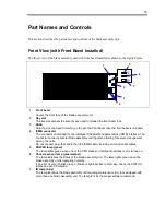
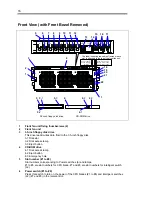
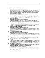
Media Select switch (Left: +, Right: –) 


The Media Select switch is provided to select the slot to connect with the floppy disk drive and 
CD-ROM drive at the front the blade assembly unit, or the USB device connected to the USB 
connector.  
The Media Select lamp of the selected slot goes on. 
Pressing the plus (+) button at the left side selects the slot one by one in ascending order   
(#1 

#2

#3

#4

#5

#6

#1).  

Pressing the minus (–) button at the right side selects the slot one by one in descending order 
(#6

#5

#4

#3

#2

#1

#6). 

17 

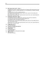
Serial Select switch (Left: +, Right: –) 


The Serial Select switch is provided to select the slot to connect with the serial device 
connected to the serial port at the front the blade assembly unit.   
The Serial Select lamp of the selected slot goes on. 
Pressing the plus (+) button at the left side selects the slot one by one in ascending order (#1 

#2

#3

#4

#5

#6

#1).  

Pressing the minus (–) button at the right side selects the slot one by one in descending order 
(#6

#5

#4

#3

#2

#1

#6). 

18 POWER 

lamp 

(Green) 


See the previous page. 

19 

Chassis sensor lamp (Green/Amber) 


See the previous page. 

20 

ID lamp (Blue) 


See the previous page. 

21 

Chassis ID switch 


Use this switch to set the ID specific to the chassis. 

22 ICMB 

connector 


See the previous page.   


Содержание N8405-013F

Страница 1: ...NEC Express5800 BladeServer Series B l a d e S e r v e r A s s e m b l y U n i t 4 U U s e r s G u i d e ...

Страница 2: ... This page is intentionally left blank ...

Страница 3: ... terms of the Warranty Statement accompanying each product However actual performance of each such product is dependent upon factors such as system configuration customer data and operator control Since implementation by customers of each product may vary the suitability of specific product configurations and applications must be determined by the customer and is not warranted by NEC To allow for ...

Страница 4: ...ding burns or property damage if the instruction is ignored Precautions and notices against hazards are presented with one of the following three symbols The individual symbols are defined as follows This symbol indicates the presence of a hazard if the instruction is ignored An image in the symbol illustrates the hazard type Attention This symbol indicates prohibited actions An image in the symbo...

Страница 5: ...Indicates a general notice or warning that cannot be specifically identified Indicates that improper use may cause loss of eyesight due to the laser beam Prohibited Actions Indicates a general prohibited action that cannot be specifically identified Do not disassemble repair or modify the blade assembly unit Not doing so can cause electric shocks or fire Mandatory Action Unplug the power cord of t...

Страница 6: ...n radiate radio frequency energy and if not installed and used in accordance with the instruction manual may cause harmful interference to radio communications Operation of this equipment in a residential area is likely to cause harmful interference in which case the user will be required to correct the interference at his own expense CE Statement Warning This is a Class A product In domestic envi...

Страница 7: ...ior written permission of NEC Corporation 2 The contents of this User s Guide may be revised without prior notice 3 The contents of this User s Guide shall not be copied or altered without the prior written permission of NEC Corporation 4 All efforts have been made to ensure the accuracy of all information in this User s Guide If you notice any part unclear incorrect or omitted in this User s Guid...

Страница 8: ......

Страница 9: ...thoroughly to fully understand the handling of the blade assembly unit and appreciate its functions to the maximum extent Text Conventions The following conventions are used throughout this User s Guide For safety symbols see SAFETY INDICATIONS provided earlier IMPORTANT Items that are mandatory or require attention when using the blade assembly unit NOTE Helpful and convenient piece of informatio...

Страница 10: ...ard Disk Drive Slots 19 Rear View 20 Rear View with Rear Fan Unit Removed 22 CPU Blade Slots 22 Intelligent Switch Slot 23 Power Unit Slot 24 Notes on the Use of KVM Media and Serial Select Switches 27 KVM Select Switch 27 Media Select Switch 28 Serial Select Switch 29 Installation 30 In the Package 30 Installing the Blade Assembly Unit 30 Check the Mounting Hardware 32 Required Tools 32 Check the...

Страница 11: ...rom the Network Serial Port 67 Floppy Disk Drive 68 Setting and Removing Floppy Disks 68 Handling Floppy Disks 69 CD ROM Drive 70 Handling the CD ROM 72 Additional Power Unit N8405 012 012F 73 Local Installation of N8400 013AF 014AF 017F 018F 019F CPU Blade 74 Items Required for Local Installation 74 Installation of Windows Server 2003 75 Upgrade installation of Windows Server 2003 from Windows 20...

Страница 12: ...iv This page is intentionally left blank ...

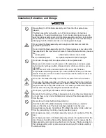
Страница 13: ...and safe operation of the blade assembly unit and server Safety Notes This section provides notes on using the blade assembly unit safely Read this section carefully to ensure proper and safe use of the blade assembly unit For more information on the symbols see SAFETY INDICATIONS provided earlier ...

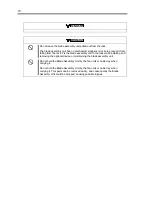
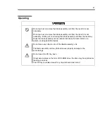
Страница 14: ...on other than described in this User s Guide Failure to follow this instruction may cause an electric shock fire as well as malfunctions of the server Do not use the blade assembly unit if any smoke odor or noise is present If smoke odor or noise is present immediately turn off the POWER switch and disconnect the power plug from the outlet then contact your service representative Using the blade a...

Страница 15: ...ination may cause a short circuit resulting in a fire Also observe the following notes when using and connecting interface cables Do not use any damaged cable connector Do not step on the cable Do not place any object on the cable Do not use the blade assembly unit with loose cable connections Do not connect interface cables with the power cord of the blade assembly unit plugged to a power source ...

Страница 16: ...ect the power plug from the outlet when a thunderstorm is approaching If it thundering starts before you disconnect the power plug do not touch any part of the blade assembly unit including the cables Failure to follow this warning may cause a fire or an electric shock Keep animals away from the blade assembly unit Failure to follow this warning may cause a fire or an electric shock Do not use a c...

Страница 17: ... unit in a place where you will need an extension cord to reach the power outlet Purchase the optional power cord set if required Using a cord that does not meet the power specifications of the blade assembly unit may heat up the cord and cause a fire Do not connect the power cord to an outlet that has an illegal number of connections The electric current exceeding the rated flow overheats the out...

Страница 18: ... the power cord Do not place any object on the power cord Do not bundle power cords Do not alter modify or repair the power cord Do not secure the power cord with staples or equivalents Do not use any damaged power cord Replace a damaged power cord with a new one of the same specifications Ask your service representative for replacement Do not use the attached power cord for any other devices or u...

Страница 19: ...mbly unit to operate incorrectly and or personal injury or damages of surrounding devices to occur Contact your service representative for the racks available for the blade assembly unit CAUTION Do not carry or install the blade assembly unit by yourself More than one person is required to carry or install the rack Failure to follow this instruction may cause the rack to fall resulting in personal...

Страница 20: ...one device from the rack at the same time may cause the rack to fall Only pull out a single device from the rack at a time Be careful when wiring the blade assembly unit not to exceed the rating of the power supply To prevent burns fires and device damages the power supplied to the power supply in the rack shall not exceed the rating load of the power branch circuit Contact your electric construct...

Страница 21: ...There is a risk of a fire due to the corrosion and the short circuits of an ternal printed board in Do not use the blade assembly unit if the covers and or fan unit is removed Do not use the blade assembly unit if the covers and or the front and rear fans in the blade assembly unit are removed Failure to follow this recommendation may decrease the cooling effect within the unit causing a malfuncti...

Страница 22: ...ssembly unit to the rack while installing and removing the optional device or maintaining the blade assembly unit Do not hold the Blade Assembly Unit by the fan units or cable tray when carrying it Do not hold the Blade Assembly Unit by the fan units or cable tray when carrying it This parts can be removed easily and consequently the Blade Assembly Unit could be dropped causing possible injuries ...

Страница 23: ... the rack may cause the blade assembly unit to operate incorrectly but also its fall on a person causing possible injuries Do not place any object on top of the blade assembly unit The blade assembly unit may fall and cause property damage to the surroundings Do not leave the CD tray open If dust accumulates on the lens of CD ROM drive the drive may have problems reading your disks The CD tray cou...

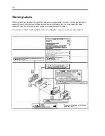
Страница 24: ... assembly unit to inform users of hazardous situations that may arise when operating the blade assembly unit Do not intentionally remove or damage any of the labels If you find any labels totally partially removed or illegible contact your service representative See Note Fixed on the bottom of the blade assembly unit ...

Страница 25: ...uninterruptible power supplies Optional power supply unit and other electronic devices These components are extremely sensitive to static electricity Make sure to touch the metal frame of the server to discharge static electricity from your body before handling the components Do not touch the hard disk drive terminals or on board parts with your hands bare and or place the hard disk drive directly...

Страница 26: ...talled power supply units creates a power redundant configuration N 1 that enables continuous operation of the system without power interruptions by an unexpected power failure In addition remote maintenance function is provided by ICMB Intelligent Chassis Management Bus interface An optional N8406 005F intelligent switch L2 supports the following functions KVM Select switch To select the CPU blad...

Страница 27: ...ent Bus ICMB interface The connector connects several blade assembly unit together allowing for server management among the units Do not connect any other cable than the ICMB cable including LAN and serial cables 5 POWER lamp green The lamp lights green when one of the CPU blades or intelligent switches L2 is turned on 6 Chassis sensor lamp green amber The lamp indicates the status of the blade as...

Страница 28: ...nch floppy disk drive CD ROM drive 1 Front fan unit fixing thumbscrews 2 2 Front fan unit 3 3 5 inch floppy disk drive This drive reads writes data from to the 3 5 inch floppy disk 3 1 Disk slot 3 2 Disk access lamp 3 3 Eject button 4 CD ROM drive 4 1 Disk access lamp 4 2 Eject button 4 3 Emergency hole 5 Slot number 1 to 8 Slot numbers corresponding to Power switches 6 and lamps 1 to 6 are slot n...

Страница 29: ...of each slot The Media Select lamp indicates the CPU blade slot 1 to 6 currently selected by Media Select switch The lamp goes on while selected and goes off when deselected The selected CPU blade can use the floppy disk drive CD ROM drive and or the USB device connected to the USB connector 12 Serial Select lamp Green 1 to 8 Located at the bottom right of the lamp group of each slot The Serial Se...

Страница 30: ...erial Select switch Left Right The Serial Select switch is provided to select the slot to connect with the serial device connected to the serial port at the front the blade assembly unit The Serial Select lamp of the selected slot goes on Pressing the plus button at the left side selects the slot one by one in ascending order 1 2 3 4 5 6 1 Pressing the minus button at the right side selects the sl...

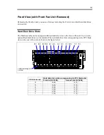
Страница 31: ... optional hard disk drives can be installed The hard disk drive slots corresponding to the CPU blade slots on the rear of the unit are shown in the figure below 1 1 0 1 1 2 0 2 1 3 0 3 1 4 0 4 1 5 0 5 1 6 0 6 1 KVM Modia 2 3 4 5 6 7 8 6 1 6 0 5 1 5 0 4 1 4 0 3 1 3 0 2 1 2 0 1 1 1 0 Label indicating slot number Hard disk drive slots corresponding to CPU blade slot CPU blade slot First slot SCSI ID ...

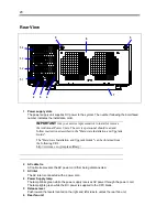
Страница 32: ...allation and Upgrade Guide The Hardware Installation and Upgrade Guide can be obtained from the following URL http www nec co jp express library 2 AC cable tie AC cable tie prevents the AC power cord from being disconnected 3 AC inlet The AC inlet is connected with a power cord 4 Power Supply lamp The lamp blinks green while the power supply receives AC power through the power cord The lamp lights...

Страница 33: ...21 7 Cable tray The cable tray protects the cable connected with the CPU blade ...

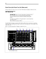
Страница 34: ...rdware Installation and Upgrade Guide The Hardware Installation and Upgrade Guide can be obtained from the following URL http www nec co jp express library The CPU blade slot located on the rear of the blade assembly unit can contain up to six optional CPU blades Insert additional CPU blades into slots in the descending order of slot numbers from right to left slots Slots 1 to 5 contain blank plat...

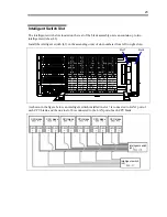
Страница 35: ...switch L2 in the ascending order of slot numbers from left to right slots Slot 7 Slot 8 As shown in the figure below an intelligent switch installed in slot 7 is connected to LAN1 port of each CPU blade and the one in slot 8 is connected to the LAN port of each CPU blade CPU blade CPU blade CPU blade CPU blade CPU blade CPU blade Intelligent switch L2 Intelligent switch L2 ...

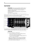
Страница 36: ...ower unit in the ascending order from bottom to top slots Slot 4 To install three or more CPU blades in the Blade Assembly Unit two or more power unit are required To install five or more CPU blades three or more power units are required IMPORTANT The power shortage error is detected when three or more CPU blades are installed in the Blade Assembly Unit with only a single power unit installed five...

Страница 37: ...erence is longer than about 10 seconds some CPU blades may not powered on automatically If the time difference between the supply of AC power to a single power unit and that to every power unit is longer than about 10 seconds at the start of the AC power supply some changes of the power supply status including the power shortage error may be recorded in the event log If the time difference between...

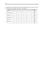
Страница 38: ...n the number of CPU blades It also shows the number of power units required for redundancy CPU blade Power slot 1 Power slot 2 Power slot 3 Power slot 4 Redundancy No First unit Yes No Second unit Yes No Third unit Yes No Fourth unit Yes No Fifth unit Yes No Sixth unit Yes ...

Страница 39: ...tartup sequence completes while the relevant KVM Select lamp being lit Selecting these devices using the KVM Select switch after the OS has started up is equivalent to the procedure to add or remove USB keyboard or USB mouse and subject to restrictions of the OS If you are going to perform any of the following operations make sure that the Media Select lamp is on the target CPU blade is selected b...

Страница 40: ...o restrictions of the OS Make sure that the floppy disk drive CD ROM drive and USB devices connected to the USB connector are not being accessed before attempting to connect a CPU blade or any other device For Windows execute Remove device safely removal of hardware before switching the blade If you are going to perform any of the following operations make sure that the Media Select lamp is on the...

Страница 41: ...nd the serial interface device connected to the serial port at the front of the blade assembly unit To disconnect the connection with the serial interface device first turn off the power of the CPU blade and that of the destination device and pull out the power cord from the destination device Failure to follow this advice may cause the devices to be defected due to the potential difference betwee...

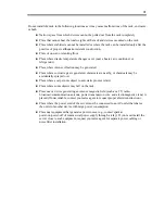
Страница 42: ...ssembly unit safely Failure to follow these instructions may result in death or serious personal injury See pages 1 to 8 for details Do not use any rack which does not conform to the relevant standard Do not use the blade assembly unit in any unapproved place CAUTION Observe the following instructions to use the blade assembly unit safely Failure to follow these instructions may cause a fire perso...

Страница 43: ... chemicals are nearby or chemicals may be accidentally sprayed over Place where a carpet not subject to anti static process is laid Place where some objects may fall on the rack Place near a device generating an intense magnetic field such as a TV radio broadcast communication antenna power transmission wire and electromagnetic crane is placed If unavoidable contact your sales agent to request pro...

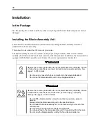
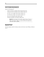
Страница 44: ... M5 washers shipped with the blade assembly unit 4 core nuts shipped with the rack assembly Template shipped with the blade assembly unit NOTE The rail brackets L and R are different from each other in shape See the figure on page 37 to check the direction and position at which each bracket is installed Required Tools The tools required to install the blade assembly unit on the rack include Philli...

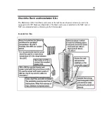
Страница 45: ...Blade Assemble Unit blade enclosure is the rack mount chassis exclusively used to be equipped with CPU blades and hard disks The blade enclosure is installed in the NEC rack or NEC recommended rack conforming to the EIA standard Installation Site ...

Страница 46: ...ts to the angle holes shown in the template fix the rail brackets L R with screws and install the blade assembly unit First confirm the installation positions of the blade assembly unit rail brackets and core nuts Installation position of core nut Installation position of rail bracket Next to the angle holes on the rack marks are made in 1U the unit indicating the height of the rack Because the bl...

Страница 47: ...ngth of each rail to the depth of the rack see the figure on the next page After assembling the rail brackets install them on the rack Align the core nut installation part with the screw hole so that the bent part at the tip of each rail bracket is projected from the rack frame Slide the rail to make the rail bracket fit to the depth of the rack When the position is determined fix the rail with th...

Страница 48: ...onnected to the option slot card Adjusting the depth of rear fan unit can increase flexibility in installation of the blade assembly unit If you do not need to change the depth of the rear fan unit use it as standard Short Standard Stretch IMPORTANT The cable for the option slot card may be unavailable when the rear fan unit is used in short setting The adjustment procedure is shown below 1 Firmly...

Страница 49: ...e rear fan unit and take out the hook parts 3 Remove five screws from top and both sides of the rear fan unit 4 Separate the rear fan unit into the front and the rear sections Take care not to apply load on the cable of the fan unit Cable Hook parts ...

Страница 50: ...stretched setting 6 Set the front and rear section of the rear fan unit so that they can be fixed to the proper position you have checked in step 5 Secure the fan unit with five screws top and side faces sides Stretched setting Short setting Short Standard Stretch ...

Страница 51: ...ith two screws as shown in the figure below In short setting you do not need to install the hook parts Keep the removed hook parts and screws for future used Stretched setting Short setting Hook parts are not necessary Install the hook parts on the bottom of the rear fan unit Hook parts ...

Страница 52: ... on the bottom of the rear fan unit is completely inserted into the frame of the cable tray Cable tray Hook 9 Enter the information on the installed rear fan unit on the Blade management sheet shipped with the blade assembly unit If a seal is shipped with the rear fan unit write down the proper information on the seal put the seal on the management seal and keep it carefully This completes the adj...

Страница 53: ...t to carry it Do not hold it by the front and rear fan units Push the blade assembly unit into the rack to the end Fix the front of the blade assembly unit with the attached large screws left and right sides See the figure below Now the blade assembly unit is completely installed on the rack The figure on the next page illustrates the installation of the blade assembly unit on the rack After all s...

Страница 54: ...w and washer Screw and washer Screw and washer Screw and washer Loosen the screw to adjust the length of rail to be fit to the depth of the rack Loosen the screw to adjust the length of rail to be fit to the depth of the rack Screw Rail bracket R Screw ...

Страница 55: ... and all the interface cables connected to the blade assembly unit 2 Remove the front bezel 3 Remove the screws fixing the front left and right sides of the blade assembly unit 4 Pull out the blade assembly unit from the rack slowly and gently IMPORTANT When the blade assembly unit is pulled out from the rack do not apply load to the unit from the top If you apply load to the blade assembly unit p...

Страница 56: ...ion For more information refer to the User s Guide of intelligent switch L2 Slot 7 Slot 8 Slot to Install an Intelligent Switch L2 The intelligent switch slots located on the rear of the blade assembly unit can contain up to two N8406 005F intelligent switches L2 As shown in the figure below an intelligent switch installed in slot 7 is connected to LAN1 port of each CPU blade and that in slot 8 is...

Страница 57: ...hese instructions may result in death or serious personal injury See pages 1 2 to 1 6 for details Do not install or remove two or more intelligent switches L2 at a time IMPORTANT In the installation of an intelligent switch with the power of the Blade Assembly Unit being on do not remove the front fan unit while the rear fan unit is removed Do not take the Blade Assembly Unit out from the rack to ...

Страница 58: ...exhausted from the fans may be at a high temperature 2 Push in on the frames at the both ends of the cable tray and lift it slightly 1 2 Cable tray Frame Frame 3 Pull the cable tray toward you and take it out of the blade assembly unit 4 Confirm the slot on which the intelligent switch L2 is to be installed ...

Страница 59: ...Hold the intelligent switch L2 so that the BP connector faces the blade assembly unit and the ejector faces downward If only one intelligent switch L2 is to be installed it must be installed in slot 7 left slot Slot 7 Intelligent switch L2 7 Insert the sides of the intelligent switch L2 board into the guide rails at the top and bottom of the blade assembly unit slowly and carefully NOTE Make sure ...

Страница 60: ... switch L2 with screws 9 Install the removed cable tray as before NOTE Make sure that the frames on both sides of the cable tray are firmly inserted and the cable tray is completely installed in the blade assembly unit 1 2 1 Ejector Cable tray Screw ...

Страница 61: ...gement function CPU1 CPU2 CPU3 connectors of BLADE switching cable A are to be connected to CPU blades in slot 1 2 and 3 respectively CPU4 CPU5 CPU6 connectors of BLADE switching cable B are to be connected to CPU blades in slot 4 5 and 6 respectively See Connection described later for details IMPORTANT The intelligent switch L2 also manages the KVM Select Media Select and Serial Select functions ...

Страница 62: ...ttom of the rear fan unit is completely inserted into the frame of the cable tray Cable tray Hook 12 Enter the information on the installed intelligent switch on the Blade management sheet shipped with the blade assembly unit If a seal is shipped with the intelligent switch write down the proper information on the seal put the seal on the management seal and keep it carefully This completes the in...

Страница 63: ...bles from the intelligent switch L2 4 Loosen a screw securing the intelligent switch L2 Screw 5 Open the ejector and take out the intelligent switch L2 from the blade assembly unit To operate the unit with the intelligent switch L2 left removed install the dummy intelligent switch L2 6 Install the removed cable guide as before 7 Install the removed rear fan and lock it to the blade assembly unit T...

Страница 64: ...e to install or remove the CPU blade The service personnel should read and follow instructions described in the Hardware Installation and Upgrade Guide The Hardware Installation and Upgrade Guide can be obtained from the following URL http www nec co jp express library ...

Страница 65: ...rd disk drive slots corresponding to CPU blade slot CPU blade slot First slot SCSI ID Second slot SCSI ID 6 6 0 6 1 5 5 0 5 1 4 4 0 4 1 3 3 0 3 1 2 2 0 2 1 1 1 0 1 1 Install a hard disk drive as described in the following procedure The following shows an example of the installation A hard disk drive can be installed in any other slot in the similar way IMPORTANT When installing a hard disk drive w...

Страница 66: ... a high temperature 4 See Additional Slot to confirm the slot on which the hard disk drive is to be installed IMPORTANT Before the hard disk drive is installed peel the label corresponding to the slot number from the slot number labels coming with the hard disk drive and put the label on the tray handle Keep the remaining labels carefully because they may be necessary when changing the configurati...

Страница 67: ... IMPORTANT Keep the removed dummy tray for future use 6 Release the lock of the lever on the hard disk drive to make the lever opened 7 Hold the hard disk drive so that the BP connector faces the blade assembly unit and the lever on the front of the drive carrier faces the top 8 Open the lever of the hard disk drive ...

Страница 68: ...he top and bottom of the blade assembly unit slowly and carefully 10 Insert the drive carrier as far as it will go and lift the lever A click occurs to lock the drive carrier Frame of blade assembly unit Lever hook NOTE Make sure that the lever hook is hung on the frame ...

Страница 69: ...ing it lightly 14 Install the removed front bezel and lock the security The installation procedure is now completed Remove a hard disk drive in the reverse of the installation procedure To remove the hard disk drive push the lever to release the lock and hold the handle securely to pull out the hard disk drive NOTE If the lamp on the front face of the drive carrier lights amber the hard disk drive...

Страница 70: ...t of the rack or to install or remove a hard disk drive IMPORTANT The front bezel cannot be removed unless the lock is released by the attached security key Installation Push the right side of the bezel to the blade assembly unit while keeping the tab at the left end of the front bezel on the frame of the blade assembly unit The installation is secure when a click occurs 1 2 Frames 2 points Tabs A...

Страница 71: ...nd of the front bezel and pull the front bezel toward you NOTE If the front bezel cannot be removed easily hold the dent at the right side of the front bezel to pull it toward you while you attempt to shift the entire front bezel to the right 3 Slide the front bezel to the left a little to remove the tab from the frame and remove the front bezel from the blade assembly unit 1 2 ...

Страница 72: ...ng the connection of the blade assembly unit to the uninterruptible power supply system or auto power controller and the time schedule operation To connect two or more blade assembly units with devices containing the ICMB bus use an ICMB connector on the front face for each connection Every device connected through the ICMB connector should have a specific chassis ID The chassis ID can be set by u...

Страница 73: ...es from the blade assembly unit before setting the chassis ID switch USB Connector To connect with the USB device connect the USB cable to the USB connector at the front of the blade assembly unit You can select the USB device or the CPU blade slot by pressing the Media Select switch on the blade assembly unit 1 1 0 1 1 2 0 2 1 3 0 3 1 4 0 4 1 5 0 5 1 6 0 6 1 KVM Modia 2 3 4 5 6 7 8 Serial Connect...

Страница 74: ...embly unit or interface cables to the CPU blade remove the rear fan unit shown in the figure below You do not need to remove the rear fan unit when connecting the power cord Release lever Push the both release levers inward and pull straightly the rear fan unit ...

Страница 75: ...onnector of CPU blade Slot 2 CPU2 connector BLADE switching cable A Combo connector of CPU blade Slot 3 CPU3 connector Product No 804 063215 001 0 Combo connector of CPU blade Slot 4 CPU4 connector Combo connector of CPU blade Slot 5 CPU5 connector BLADE switching cable B Combo connector of CPU blade Slot 6 CPU6 connector Product No 804 063215 002 0 CPU BLADE Connector Intelligent Switch L2 Connec...

Страница 76: ...PU blade slot 4 CPU blade slot 5 CPU blade slot 8 Intelligent switch L2 slot 7 CPU BLADE 4 5 6 CPU BLADE 1 2 3 KVM connector CPU1 CPU2 CPU3 CPU4 CPU5 CPU6 COMBO connector KVM cable Output VIDO USB BLADE switching cable B BLADE switching cable A CPU1 NOTE The BLADE switching cable A is longer than B A label indicating 804 063215 001 00 is attached to the BLADE switching cable A A label indicating 8...

Страница 77: ...ral and or interface cable supplied by a vendor other than NEC third party first ask your service representative whether the device is compatible with the Blade Assembly Unit Some third party devices are not compatible with the Blade Assembly Unit Fix the power cords and interface cables with cable ties so that they cannot get caught Route the cables so that they cannot touch the rack door and the...

Страница 78: ...15 seconds the blade assembly unit may not power on In this case turn on the power of the blade assembly unit by using the POWER switch after making sure that the AC power is supplied to every power unit Powering ON from the Blade Assembly Unit Press one of the POWER switches on the front panel of the Blade Assembly Unit If the power is turned on it is supplied to the CPU blade and hard disk drive...

Страница 79: ...00 020F 021F 022F CPU blade N8400 013AF 014AF 017F 018 019F CPU blade Powering ON from the Network Serial Port Depending on the BIOS setting of the CPU blade the power of the CPU blade may be automatically turned on by a proper packet received from the network or via the modem connected to the serial port This power on procedure can be specified by setting Wake On Events of System Hardware in the ...

Страница 80: ...oppy disk into the floppy disk drive the drive clicks and the eject button on the floppy disk is slightly pushed out To eject the floppy disk from the floppy disk drive press the eject button NOTES When an unformatted floppy disk is inserted a message notifying that date read is not available and a message prompting formatting are displayed Refer to the manual that comes with the OS for more infor...

Страница 81: ...agnet Do not pinch the floppy disk with a paper clip or drop it Keep the floppy disk in a floppy disk case that protects it from magnetism and dust A floppy disk has a write protect switch that prevents the stored data from accidental erasure You can read data from a write protected floppy disk but you cannot save data into the floppy disk or format it NEC recommends that you should write protect ...

Страница 82: ...ered the POWER lamp is lit before inserting a CD ROM into the CD ROM drive 2 Press the Eject button on the front of the CD ROM drive The tray comes out a little 3 Put the CD ROM on the tray carefully and securely with the character printed surface facing upward 4 Push the front of the tray lightly to retract it into the drive IMPORTANT If a noisy sound in driving the CD ROM drive occurs after sett...

Страница 83: ...imately 1 2 mm in diameter and 100 mm in length into the emergency hole on the right front of the CD ROM drive You can use a straightened large paper clip as a substitute Then gently push it in until the tray is ejected Emergency hole IMPORTANT Do not use a toothpick or plastic stick that could easily break If the above procedure does not let you take out the CD ROM contact your service representa...

Страница 84: ... the CD ROM with its printed side upward and gently put it on the tray Do not scratch the CD ROM or write anything directly on it with a pencil or ballpoint pen Keep the CD ROM away from cigarette smoke Do not leave the CD ROM in a high temperature place e g place exposed to direct sunlight or close to a heater When dust or fingerprints are attached on the CD ROM wipe the CD ROM from its center to...

Страница 85: ...stall or remove the Additional Power Unit N8405 012 012F The service personnel should read and follow instructions described in the Hardware Installation and Upgrade Guide The Hardware Installation and Upgrade Guide can be obtained from the following URL http www nec co jp express library ...

Страница 86: ...tion using the internal floppy disk drive and CD ROM drive of N8405 013F blade assembly unit Before starting the job prepare the following items including disks and manuals For Windows Server 2003 User s Guide this document First Step Guide NEC EXPRESSBUILDER CD ROM Microsoft Windows Server 2003 Standard Edition CD ROM For Windows 2000 User s Guide this document First Step Guide NEC EXPRESSBUILDER...

Страница 87: ...ices installed in your system or you have chosen to manually specify an adapter Currently Setup will load support for the following mass storage devices The following message appears Please insert the disk labeled manufacturer supplied hardware support disk into Drive A Press ENTER when ready 5 Insert the Windows Server 2003 OEM DISK for NEC EXPRESSBUILDER into the floppy disk drive and select Ada...

Страница 88: ...rom Windows 2000 Follow these steps to upgrade your Windows 2000 to Windows Server 2003 1 Turn on the system and start Windows 2000 2 Log on to the system using a username of Administrator authority 3 Insert the Windows Server 2003 CD ROM or the back up CD ROM into the CD ROM drive which is connected to the CPU Blade The Select the operation executed screen appears NOTE If the Select the operation...

Страница 89: ...ss ENTER when ready 8 Insert Windows Server 2003 OEM DISK for NEC EXPRESSBUILDER into the floppy disk drive and select Adaptec Ultra320 SCSI Cards Win XP Server 2003 IA 32 The following message appears The driver you provided seems to be newer than the Windows default driver Windows already has a driver that you can use for Adaptec Ultra320 SCSI Cards Win XP Server 2003 IA 32 Unless the device man...

Страница 90: ... drive 2 Turn on the power to start the CPU blade 3 Press F6 while the message Setup is inspecting your computer s hardware configuration appears at the top of the screen NOTES In this status pressing F6 cannot change the screen display at all Conduct key entries when the access lamp on the USB floppy disk drive is off or access to the floppy disk does not occur 4 If the following message appears ...

Страница 91: ... Then continue the proper jobs following the on screen instructions Refer to the First Step Guide for details of the installation After the files have been copied the system restarts automatically Then provide the setup following the on screen instructions Refer to the First Step Guide for details Once the installation is complete go to Jobs to Perform after Installation Jobs to Perform after Inst...

Страница 92: ... 2000 the proper driver must be installed in the following steps Prepare Windows 2000 Driver for Internal Floppy Disk Drive CD ROM provided with the blade assembly unit 1 When the Media Select lamp of the CPU blade on which Windows 2000 is installed lights for the first time the following dialog will appear prompting you to install the driver 2 Click Next ...

Страница 93: ...or a suitable driver for my device recommended radio button and click Next 4 Insert the Windows 2000 Driver for Internal Floppy Disk Drive CD ROM into the CD ROM drive Put a checkmark on CD ROM drives only and then click Next ...

Страница 94: ...82 5 When the driver is detected from the CD ROM click Next 6 Click Finish This completes the installation ...

Страница 95: ...012F is mounted Frequency 50 60 Hz 1 Hz Power supply 1 AC inlet 1 4 Cooling fan 2 hot swappable External dimensions 440 W 886 D 177 mm 4U Power consumption 3564W maximum configuration Weight 31 kg 73 kg in maximum configuration Operating Temperature 10 to 35 C Operating Humidity 20 to 80 RH no condensation 1 Power Supply Unit is necessary option N8405 013F BladeServer Assembly Unit has no Power Su...

Отзывы: