47
5.
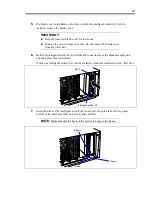
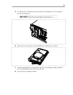
If a blank cover is installed on the slot on which the intelligent switch (L2) is to be
installed, remove the blank cover.
IMPORTANT:
Keep the removed blank cover for future use.
Remove the cover of target slot only. Do not remove the blank cover
from any other slot.
6.
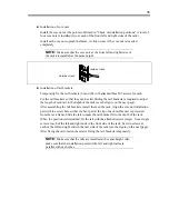
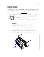
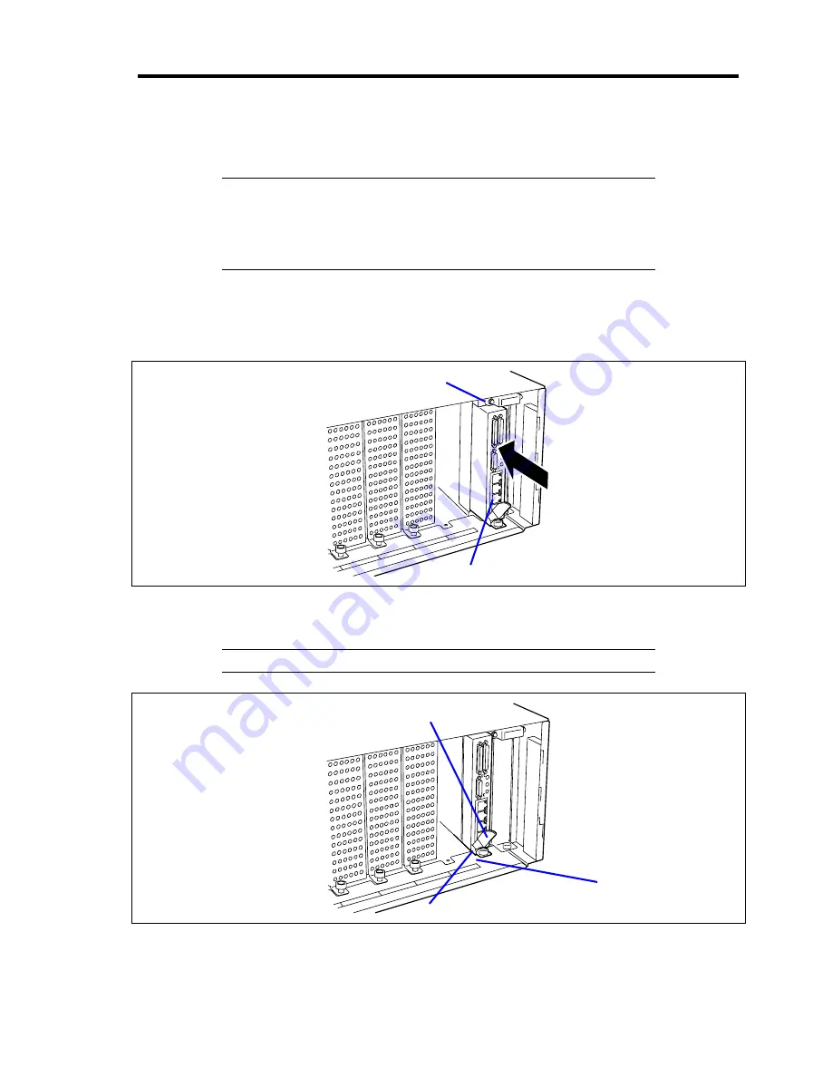
Hold the intelligent switch (L2) so that the BP connector faces the blade assembly unit
and the ejector faces downward.
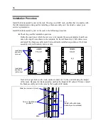
If only one intelligent switch (L2) is to be installed, it must be installed in slot 7 (left slot).
Slot 7
Intelligent switch (L2)
7.
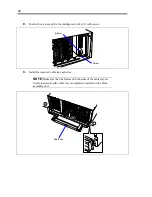
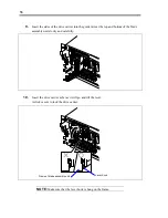
Insert the sides of the intelligent switch (L2) board into the guide rails at the top and
bottom of the blade assembly unit slowly and carefully.
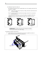
NOTE:
Make sure that the hook of the ejector is hung on the frame.
Ejector
Frame
Hook
Содержание N8405-013F
Страница 2: ... This page is intentionally left blank ...
Страница 8: ......
Страница 12: ...iv This page is intentionally left blank ...
Страница 33: ...21 7 Cable tray The cable tray protects the cable connected with the CPU blade ...
Страница 94: ...82 5 When the driver is detected from the CD ROM click Next 6 Click Finish This completes the installation ...

