15
Part Names and Controls
This section describes the part names and controls of the blade assembly unit.
Front View (with Front Bezel Installed)
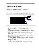
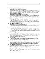
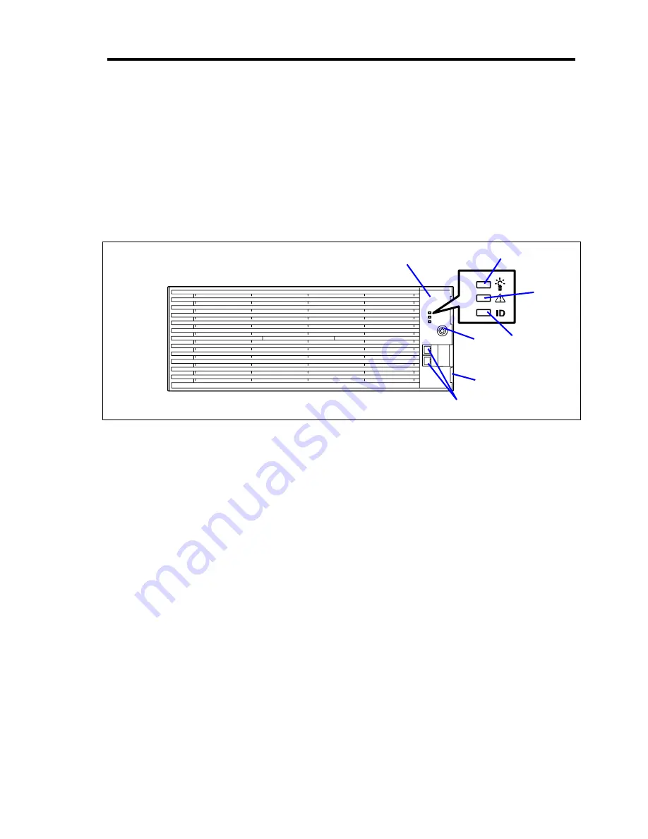
The front view of the blade assembly unit with front bezel installed is shown in the figure below.
1
5
7
2
3
4
6
1 Front
bezel
Covers the front face of the blade assembly unit.
2 Key
slot
The key slot accepts the security key used to release the front bezel lock.
3 Knob
Hold the dent and pull it toward you to open the front bezel once the front bezel is unlocked.
4 ICMB
connector
The connector is intended for the Intelligent Chassis Management Bus (ICMB) interface. The
connector connects several blade assembly unit together, allowing for server management
among the units.
Do not connect any other cable than the ICMB cable, including LAN and serial cables.
5 POWER
lamp
(green)
The lamp lights green when one of the CPU blades or intelligent switches (L2) is turned on.
6
Chassis sensor lamp (green/amber)
The lamp indicates the status of the blade assembly unit. The lamp lights green when the
blade assembly unit is operating normally.
If an error occurs, it blinks green or blinks or lights amber. In this case, check the STATUS
lamps on each CPU blade.
7
ID lamp (blue)
The lamp identifies the blade assembly unit requiring maintenance in a rack equipped with
more than one blade assembly unit. The lamp is lit by the proper software command.
Содержание N8405-013F
Страница 2: ... This page is intentionally left blank ...
Страница 8: ......
Страница 12: ...iv This page is intentionally left blank ...
Страница 33: ...21 7 Cable tray The cable tray protects the cable connected with the CPU blade ...
Страница 94: ...82 5 When the driver is detected from the CD ROM click Next 6 Click Finish This completes the installation ...

