


63
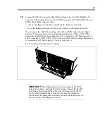
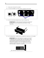
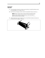
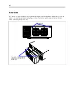
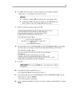
Save cables in the cable tray to be routed to the outside so that they may not disturb the installation
of the rear fan unit.
Cable tray
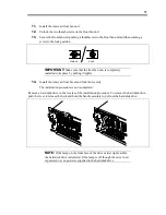
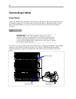
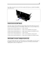
Combo Connector (CPU Blade)
Connect the combo connector at the front of the CPU blade to the CPU BLADE connector at the
front of the intelligent switch (L2) with the BLADE switching cable A or B (see the figure below).
Combo connector of CPU blade (Slot 1)
←→
CPU1 connector
Combo connector of CPU blade (Slot 2)
←→
CPU2 connector BLADE switching cable A
Combo connector of CPU blade (Slot 3)
←→
CPU3 connector (Product No. 804-063215-001-0)
Combo connector of CPU blade (Slot 4)
←→
CPU4 connector
Combo connector of CPU blade (Slot 5)
←→
CPU5 connector BLADE switching cable B
Combo connector of CPU blade (Slot 6)
←→
CPU6 connector (Product No. 804-063215-002-0)
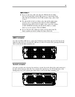
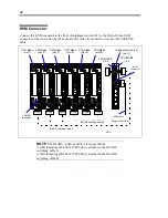
CPU BLADE Connector (Intelligent Switch (L2))
Connect the CPU BLADE connector (CPU BLADE 1-2-3 and CPU BLADE 4-5-6) at the front of
the intelligent switch (L2) to the combo connector at the front of CPU blade with the BLADE
switching cable A or B (see the figure below).
Содержание N8405-013F
Страница 2: ... This page is intentionally left blank ...
Страница 8: ......
Страница 12: ...iv This page is intentionally left blank ...
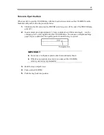
Страница 33: ...21 7 Cable tray The cable tray protects the cable connected with the CPU blade ...
Страница 94: ...82 5 When the driver is detected from the CD ROM click Next 6 Click Finish This completes the installation ...


