background image

Page 58   P/N 03521015 Rev U1     

Bio-Medical Devices Intl  

 17171 Daimler Street    Irvine, CA 92614    800-443-3842    www.maxair-systems.com

2600-01 LED Indicator and Charge Status

Fast charge (Red LED)

- The charger is in constant current mode.

- Charge current is at the maximum.

Final charge (Red LED)

- The charger is in constant voltage mode.

- Charge current is less than the maximum.

- The battery is normally 80-95% charged.

- The charger stays in this mode until the charge 

   current decreases to charge termination level.

Charge completed (Green)

- The charge is stopped.

- Charge current is zero.

Charging Diagram

Charging Protection from Electrical Surges

It is highly recommended to always connect the MAXAIR Charger directly to a Surge Protection Device, adequate for all  

anticipatable occurrances, during all charging activities of MAXAIR LIBs, and whenever the Charger is connected to a mains 

power source.

To choose an appropriate surge protector you should consult with your Engineering department regarding specifics to your 

physical plant and geographical environment. You may want to consider the following common fundamentals - 

▲Indicator light – surge protectors will not last forever – when a surge protector properly diverts a surge, the protector itself can 

be damaged in the process. An indicator light will indicate that the surge protector is working fine.

▲UL Rating - good surge protectors come with a UL rating (or equivalent regulatory mark for non U.S. countries, e.g. CE Mark, 

etc.), a rating put out by the independent Underwriters Laboratories that tests the safety of electronic devices. 

▲Clamping voltage - the voltage measurement that prompts the surge protector to start redirecting the excess electricity away 

from the plugged-in devices. 

▲A surge protector with a lower clamping voltage will trigger earlier, thus better protecting electrical devices. 

▲Joule rating - the maximum amount of energy the surge protector can absorb. If the surge exceeds this maximum, the surge 

protector will be rendered useless. The higher the joule rating, the more energy can be absorbed by the surge protector, 

therefore, a higher joule rating will often indicate a longer lifespan for the product. 

2600-02 LED Indicator and Charge Status

Step 1 - Constant Current Charge cycle starts automatically 

when connected to mains and battery is connected to char-

ger. Charging is with maximum charger current. The LED is 

YELLOW. This allows rapid charging to 80-95% capacity. 
Step 2 - Constant Voltabe (Timer) Charge. Charge voltage 

is constant and charge current is decreasing. The LED is 

FLASHING YELLOW. This continues until current has de-

creased to end of charge detection level of until Timer runs 

out (8 hours). The battery is charged to full capacity. 
Step 3 - Charge Complete. The LED turns GREEN, the 

battery is fully charged, the charge current is zero, and the 

battery has been charged to its full capacity. A new charge 

cycle will be initiated if battery voltage decreases with 0.1 V/

cell. 

FLASHING GREEN - Battery not connected.

3 Red Blinks - Charger output is shorted.

4 Red Blinks - Battery voltage low and may need replacing.

Содержание CA-CAPR-36

Страница 1: ...P N 03521015 Rev U1 Page 1 User s Instructions CAPR Systems...

Страница 2: ...949 752 9642 Fax 949 752 9658 Website www maxair systems com E mail info maxair systems com Shipping Mailing Address Bio Medical Devices Intl 17171 Daimler Street Irvine CA 92614 USA IMPORTANT Please...

Страница 3: ...e 1 800 443 3842 for a Return Material Authorization RMA number If it is determined that the product may be defective BMDI Customer Service will provide an RMA number and instructions for product retu...

Страница 4: ...29 3 7 2365 02SM ML 01031291 01031316 Overview 29 3 8 Battery Belt and Charger Overview 30 4 Decontamination Cleaning 31 5 General System Maintenance and Storage 32 6 Battery Use Maintenance and Stora...

Страница 5: ...n Battery 56 13 Charger 57 14 Helmet 60 15 Helmet Liner 61 16 Filter Cartridge 63 17 Filter Cover Cap FCC 64 18 Disposable Lens Cuff DLC 66 19 DLC Shroud 74 20 DLC Double Shroud 78 21 HE DLC Pre Filte...

Страница 6: ...ained per the User s Instructions Failure to follow the User s Instructions may be hazardous to the user s health NIOSH Cautions and Limitations A Not for use in atmospheres containing less than 19 5...

Страница 7: ...ent that could cause the Helmet to become dislodged from the users head and result in loss of respiratory protection Materials of HFR Hoods are tested per ASTM F1671 and AATCC 127 to provide an indica...

Страница 8: ...Page 8 P N 03521015 Rev U1 Bio Medical Devices Intl 17171 Daimler Street Irvine CA 92614 800 443 3842 www maxair systems com 1 3 SYMBOLS General and Packaging...

Страница 9: ...ION The purchaser user is responsible for determining the appropriateness of the CAPR System for each any of their particular applications environments 2 Regulatory Marking Definitions Filter markings...

Страница 10: ...Liner and Power Cord 2083 03 03531001 Blower Assy 03531148 Liner 01031269 Cage 2590 05 Power Cord POWER CORDS POWER CORD Turnlock 2590 05 2590 05 LINERS LINER Standard 2071 06 03531021 LINER ChinBar...

Страница 11: ...HOOD WITH FILTER 2270 06SM 07831038 XP HFR DLC SINGLE HOOD WITH FILTER 2271PW 07ML 07831184 XP HFR DLC SINGLE HOOD WITH FILTER 2271PW 07SM 07831183 XP HFR DLC SINGLE HOOD WITH FILTER 2271PB 07ML 0783...

Страница 12: ...ER DESCRIPTION CARTRIDGE FILTER NIOSH 2164 10 HE 01031327 2163 10 XP 01031279 2167 10 XP 01031569 2166 10 XP 01031593 2081 03 P Ns 03531001 03531021 01031269 2590 05 Helmet with Cage w o Cage w o Cage...

Страница 13: ...M 01031394 DLC Double Shroud Small Table 2 Approved System Components cont d BATTERY CHOICE S PER FILTER CHOICE 01532104 2500 36TSC 36TSC 01532161 37TSC 37TSC 37TSC 01532116 30TSC 30TSC 30TSC 30TSC HO...

Страница 14: ...7 07831205 XP HFR Double Hood HLF Filter 2272PW 07SM 07831025 2170 27 07831205 XP HFR Double Hood HLF Filter 2272PB 07ML 07831202 2170 27 07831205 XP HFR Double Hood HLF Filter 2272PB 07SM 07831173 21...

Страница 15: ...Charger 2600 02 01432202 Single Charger NOTE The Battery Belt and Single Chargers are approved for use with all items that are indicated in Table 2 NOTE Use of Gang Charger and Bracket do not require...

Страница 16: ...lable including 2500 36TSC typically 8 10 hours charge 2500 37TSC typically 12 15 hours charge Two Helmet Assembly choices are available including 2081 03 the standard CAPR Helmet Assembly for general...

Страница 17: ...d Remove 2167 10 HE Filter Cartridge1 2061 08 Filter Cover Cap 2260 05ML or SM Shroud 4 3 2365 02 ML or SM Cuff Shroud HE or XP Cuff HE 2051 07 CAGE 2081 03 HELMET w o CAGE 8 6 7 2261 01ML or SM Doubl...

Страница 18: ...e 18 P N 03521015 Rev U1 Bio Medical Devices Intl 17171 Daimler Street Irvine CA 92614 800 443 3842 www maxair systems com The alternate 2600 02 Single Charger may be substituted in place of the 2600...

Страница 19: ...e 19 P N 03521015 Rev U1 Bio Medical Devices Intl 17171 Daimler Street Irvine CA 92614 800 443 3842 www maxair systems com The alternate 2600 02 Single Charger may be substituted in place of the 2600...

Страница 20: ...e 20 P N 03521015 Rev U1 Bio Medical Devices Intl 17171 Daimler Street Irvine CA 92614 800 443 3842 www maxair systems com The alternate 2600 02 Single Charger may be substituted in place of the 2600...

Страница 21: ...e 21 P N 03521015 Rev U1 Bio Medical Devices Intl 17171 Daimler Street Irvine CA 92614 800 443 3842 www maxair systems com The alternate 2600 02 Single Charger may be substituted in place of the 2600...

Страница 22: ...does not include these snaps A or the front adapter B and must not be used with the DLC Shroud and DLC Double Shroud 2260 05ML SM and 2261 01ML SM respectively When upgrading older DLC CAPR Systems t...

Страница 23: ...chase a 2500 Series LIB you will receive new power cords for each of the MAXAIR Helmets you have purchased over time You must discard all older power cords when you receive your new 2500 Series LIBs t...

Страница 24: ...1021 01031269 2590 05 Helmet Assembly consisting of Helmet Liner Cage Power Cord 2 2051 07A B 01031269 Cage SnapOn 3 2071 06A 03531021 Liner 4 2590 05A 2590 05 Power Cord 5 2500 36TSCC 01532104 Li Ion...

Страница 25: ...icators 4 Front snaps for Liner 5 Front Headband Comfort Strip 6 Front Liner Pads 7 Side Adapters 8 Side Tabs 9 Side Adjustment Straps with Snaps 10 Rear Liner Pads 11 Helmet Label 12 Rear snaps for L...

Страница 26: ...83 03 2083 03 w o Cage 03531153 Blower Assembly 2051 07 SnapOn Cage 2071 06 Liner 2071 02 ChinBar Liner 2071 05 Liner Hard Hat 2590 05 Power Cord Helmets Summary 3 6 2 Helmet Assemblies 2083 03 Helmet...

Страница 27: ...If the Yellow LED is lit check the Filter Cartridge for excess particulate dirt build up and damage and replace if necessary The Battery charge level is indicated by the three Green and one Red LEDs...

Страница 28: ...ange of air flow to me work activity and personal comfort CAUTION The Air Flow Switch is user adjustable to match the amount of air flow with the user s activity level and breathing requirements NOTE...

Страница 29: ...fined as follows 3 7 2365 02SM ML 01031291 01031316 Overview Identify familiarize and understand the following key items 1 Side Attachment Holes 2 Front Attachment Hole 3 Flappers 4 Lens 5 Cuff 6 Peel...

Страница 30: ...lip 2 Power Cord Connector Socket 3 Secure Lock Pushbutton 4 Adjustable Belt 5 Belt Clip 6 Charger LED Status 7 Charger Battery Connector Plug Characteristics 1 Attaches to Adjustable Belt or clothing...

Страница 31: ...g wipe Decontaminating Agent Alcohol bleach or quaternary ammonia Wipe between uses and between different users wearing the system Reduces cross contamination Extends useful life Improves hygiene Proc...

Страница 32: ...repeated assembly disassembly so as to compromise its attachment mechanism or causes the Helmet mounting to be unstable and if there are any tears or breaks in the Liner the Helmet Liner should be rep...

Страница 33: ...e Shrouds and Hoods The DLC LIne of Face and Head Covers is designed for single use once on once off the Helmet Repeated assembly and disassembly will compromise the attachment mechanism or cause the...

Страница 34: ...XAIR LIB and replace the Suspect LIB as soon as possible Check LIBs that are connected to MAXAIR chargers on a daily basis If the charger LED is green the LIB is ready for use and should be disconnect...

Страница 35: ...r conduction cookware 7 Do not expose a LIB to water salt water any other liquid or moisture beyond air with a relative humidity between 10 90 8 Do not connect the connection terminals together even m...

Страница 36: ...t rupture or ignite Always charge in an isolated area away from flammable materials When charging LIBs always monitor the charging process and react to potential problems that may occur 6 3 4 Store WA...

Страница 37: ...tery test The helmet and power cord must be in good working order Set the helmet Air Flow Switch to Low for the test CAUTION If the LIB performs in one of the Suspect LIB categories below discontinue...

Страница 38: ...onment You may want to consider the following common fundamentals Indicator light surge protectors will not last forever when a surge protector properly diverts a surge the protector itself can be dam...

Страница 39: ...apsed from Manufacture Date Self Discharge Loss Permanent Capacity Loss Self Discharge Loss Permanent Capacity Loss 23 C 60 C 23 C 60 C 23 C 60 C 23 C 60 C 1 4 24 1 8 10 40 6 20 2 8 48 2 16 20 80 12 4...

Страница 40: ...for medical waste and current local regulations Lithium Ion Rechargeable Batteries contain toxic chemicals and must be disposed of following current local regulations and your local recycling program...

Страница 41: ...signs of physical damage Assemble the Helmet into the desired configuration and verify that it is fully functional Report any damage to the shipper immediately for resolution Follow similar procedure...

Страница 42: ...to a fully assembled CAPR Helmet with Filter Cartridge and Filter Cover Cap or Hood to verify that it powers the Helmet and that at least one Green LED lights Report any damage or non function to the...

Страница 43: ...acking the 2000 76 Battery Belt Carefully unpack the 2000 76 Battery Belt from the shipping bag Verify there are no missing or loose components and that the Belt shows no signs of physical damage Repo...

Страница 44: ...damage Connect the Charger to a working wall outlet and verify that the Green LED is lit Connect the Charger to a Battery that powers a MAXAIR Helmet with either a red LED or one or two Green LEDs lit...

Страница 45: ...s with your right hand Tear off the small bottom end piece at its perforation line 6 When finished the dispensing box should be as shown above 7 To Dispense merely reach in and grasp the end of the to...

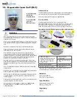
Страница 46: ...800 443 3842 www maxair systems com There are two sizes of DLCs The ML is for most users The SM is for those with small head sizes ITEM O N PN QTY EA DESCRIPTION 1 2365 02SM 01031316 40 DLC Disposable...

Страница 47: ...ty Status Indicator LEDs See Section 6 for more detail 4 Check to ensure that the Helmet Power Cord is firmly attached to the Helmet Power Cord Connector 9 3 Assemble and Disassemble Components CAUTIO...

Страница 48: ...ions all components are expected to provide reliable service for their full useful life 9 4 Inspections 9 5 Warning Device Yellow LED Air Flow Indicator Check Bouffant Cap Method CAUTION In preparatio...

Страница 49: ...uffant Cap gap 4b As soon as the Yellow LED turns on in less than five seconds open the Bouffant Cap approximately 4 to 5 10cm to 12cm Notice the Yellow LED turns off Close the gap of Bouffant Cap 5 D...

Страница 50: ...ow LED Air Flow Indicator Check Tape Method CAUTION Prior to donning the system the Safety Status Yellow LED function can and should be checked prior to use The yellow LED indicates that the respirato...

Страница 51: ...ticularly with regards to battery charger helmet adjustments and facial fit Differences for other configurations are covered in the respective sections for those other face and head covers 1 Obtain th...

Страница 52: ...that both tabs are in the same hole position CAUTION Optimum setting is achieved when the helmet is secure on the head for all movements re quired and the front headband is within 1 2 inch of the eyeb...

Страница 53: ...nnect the Helmet Power Cord from the Battery push the Secure Connection Button down pull Cord Connector out release the Button 4 Disconnect the Battery Belt from around the waist by un snapping the bu...

Страница 54: ...urnClip horizontally 5 Loosen the rear Headband Adjustment Knob by turning it counterclockwise 7 Follow steps 3 7 from Alternative A 2 Grasp each side DLC at the Flappers pull outware and unsnap DLC f...

Страница 55: ...d may easily be cleaned with a decon wipe and reused until worn or otherwise unsuitable for use 1 To remove a damaged or soiled Rear Comfort Strip pull it away and off of the Headband 2 To attach a ne...

Страница 56: ...connected to charger for more than 10 seconds 3 Place the belt comfortably around the waist with the battery near the side back of the right hip To initiate air flow connect the Helmet Power Cord to...

Страница 57: ...manufacturer s agent 6 A fuse protects the Charger against short circuiting and overloading 7 This symbol means that the charger is double insulated Insulation Class II 8 If the Charger is mounted in...

Страница 58: ...countries e g CE Mark etc a rating put out by the independent Underwriters Laboratories that tests the safety of electronic devices Clamping voltage the voltage measurement that prompts the surge pro...

Страница 59: ...unt them to a wall cabinet etc use the mounting hardware supplied Charging Batteries with the 6 Gang Battery Charger Plug the power cord into a standard 110v outlet If necessary connect from one to si...

Страница 60: ...the rear Snap Tab and remove the SnapOn Cage lifting upward and off the Helmet 3 The helmet is ready to assemble the appropriate Filter Cartridge Air Flow Switch Position Low Med High Air Flow in Lite...

Страница 61: ...t with one hand and position the Liner inside the Helmet Adjust the power cord over the power cord slot 2 Align and place the Liner front bottom edge under and against the front lip of the Helmet 3 Fr...

Страница 62: ...with the Adjustment Knob for optimizing the circumference of the Headband It also aids in proper positioning for easy visualization of the LED Safety Status Indicators If necessary unsnap the Height A...

Страница 63: ...r Cartridge rear Tab in place onto the Helmet rear upper Snap 3 Center and lift the left and right side Filter Cartridge Snap Tabs such that they sit on top of the Helmet side upper Snaps 4 Using the...

Страница 64: ...Cover Cap 2061 08 01031284 provides protection for MAXAIR Filter Cartridges in various Cuff and Shroud configurations Asssembly 2 Hold the FCC in one hand and insert the front Adapter of the Helmet Li...

Страница 65: ...inst the FCC and the fingers on the inside of the Helmet With the other hand pull up on the FCC T Tab and unlatch it from the Helmet FCC Rear Bottom Snap 2 Continue pulling up on the T Tab with one ha...

Страница 66: ...Intl Inc does not recommend the appropriate systems for a particular institution or facility DO NOT use if any component is damaged If any com ponents are damaged or contaminated and therefore unfit...

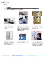
Страница 67: ...face to the outside of the Helmet Assembly before donning the Helmet 1 Obtain the appropriate DLC from the DLC dispensing box 2 Align FCC front TurnClip horizontally snap the DLC Front Alignment Hole...

Страница 68: ...institution s protocol for contaminated waste 3 Grasp the center of the DLC and lift away from the TurnClip 2 Grasp both side DLC Flappers and lift out and away from the FCC Side Attachment Posts 3 Co...

Страница 69: ...ff the Lens 5 Align and Snap the other DLC Side Attachment Hole over the other FCC Side Attachment Post WARNING After donning if conditions 1 and 2 both are not achieved switch to the other size DLC a...

Страница 70: ...m the DLC dispensing box and attach the DLC Lens with the DLC cuff facing the inside to the helmet Remove the DLC Protective film 4 Connect the Helmet Power Cord to the Battery Push the Power Cord Con...

Страница 71: ...LED Safety Status Indicators If necessary unsnap the Height Adjustment tabs on each side of the Helmet Liner and reposition upward or downward until the optimum fit for comfort and security is determ...

Страница 72: ...Connection Button down pull Cord Connector out release the Button 4 Disconnect the Battery Belt from around the waist by un snapping the buckle 5 With the Charger connected to the mains wall power con...

Страница 73: ...s time 7 Disconnect the Helmet Power Cord from the Battery push the Secure Connection Button down pull Cord Connector out release the Button 6 Hold the front top of the Helmet in one hand and with the...

Страница 74: ...es not recommend the appropriate systems for a particular institution or facility DO NOT use if any component is damaged If any compo nents are damaged or contaminated and therefore unfit for safe and...

Страница 75: ...nap snap and secure Disassembly Reverse Asssembly steps to remove Shroud from Helmet WARNING Dispose of contaminated Shrouds according to institutional protocol for contaminated waist CAUTION Read Sec...

Страница 76: ...ront headband within inch of eyebrows for visualization of the Safety LEDs WARNING After donning if conditions 1 and 2 both are not achieved switch to the other size DLC and repeat the Assembly and Do...

Страница 77: ...10 Pull neck ties around to the front and tie securely leaving about a inch gap between neck and Shroud Pull waist ties around and tie in front 8 Continue pulling Shroud down all around Doffing Revers...

Страница 78: ...lth IDLH and atmospheres containing less than 19 5 oxygen Follow current local regulations governing biohazard waste to safely dispose of used shrouds If you need more information contact your BMDI Sa...

Страница 79: ...Shroud front Mounting Hole over TurnClip Turn TurnClip vertically to secure the attachment 5 Snap one side of DLC onto one side FFC Attachment Post then snap other side 2 Grasp top of DLC Cuff and pu...

Страница 80: ...secure as comfortably possible while ensuring stability 7 Pull back of shroud up and over the Helmet Slide fingers between face and cuff on both sides from chin to temples to ensure slight Cuff to Fa...

Страница 81: ...doff Helmet and remove Shroud After disconnecting the Battery from the Helmet connect it to the Charger 9 Lift outer shroud up so that you can pull the inner shroud neck ties around to the front and t...

Страница 82: ...NOT for use in atmospheres immediately dangerous to life or health IDLH and atmospheres containing less than 19 5 oxygen Follow current local regulations governing biohazard waste to safely dispose o...

Страница 83: ...met DLC Cuff facing in 4 Snap front of Hood DLC to center Helmet snap 5 Snap other side of Hood DLC to other side snap of Helmet 6 Grasp Hood Snap Tab and begin pulling hood up and over helmet 7 Conti...

Страница 84: ...Slide fingers between face and Cuff on both sides from chin to temples to ensure slight Cuff to face tension 16 Ensure that the front Headband is within 1 2 inch of eyebrows for good visualization of...

Страница 85: ...vel I fabric may burn if exposed to open flame Follow current local regulations governing biohazard waste to safely dispose of used shrouds If you need more information contact your BMDI Sales Represe...

Страница 86: ...hment post 7 Attach center Hood Lens align ment hole over Helmet center alignment post 8 Attach other Hood Lens attach ment hole to other Helmet side attachment post Don 2 Connect the Battery to the B...

Страница 87: ...p over and down below Helmet in back 12 Continuing process of 11 pull Hood all the way down so that Hood Filter blue is fully down on Helmet CAUTION If conditions in 9 and 10 are not achieved switch t...

Страница 88: ...o not contaminate Helmet gown or wearer Doff 21 Discard Hood and HLF per institutional protocol for contaminated waste 18 Grasp both Body Ties and pull up to bring back bottom of Hood up and over Helm...

Страница 89: ...se they should be replaced immediately Only trained and experienced personnel who have read and under stand the User s Instructions should use this product Failure to follow the User s Instructions th...

Страница 90: ...nap one side of Quick Cuff to an appropriate Helmet Headband Snap Hole 4 Snap other side of Quick Cuff to a same positioned Helmet Headband Snap Hole on the other side of Helmet 7b For 2026 03 Helmet...

Страница 91: ...xposed to open flame Follow current local regulations governing biohazard waste to safely dispose of used shrouds If you need more information contact your BMDI Sales Representative or call BMDI custo...

Страница 92: ...tery and then completed or fully after the battery is donned and connected NOTE Depending on the anticipated comfort level when fully gowned the Helmet Air Flow Level may be set to Med of High 1 2 inc...

Страница 93: ...270 06SM may be more appropriate 10 Holding the Helmet securely on head grasp back bottom of Hood Skirt and pull up over and down below Helmet in back 11 Continuing process of 11 pull Hood all the way...

Страница 94: ...d up and over Helmet 24 Doff and discard gown per gown supplier protocol 18 Ensure Hood Skirt is fully down on all sides Secure Neck ties to within about 1 2 inch of neck Secure body ties around waist...

Страница 95: ...OSH approved compatible components NOT for use in atmospheres immediately dangerous to life or health IDLH and atmospheres containing less than 19 5 oxygen or more than 25 oxygen If you need more info...

Страница 96: ...y MAXAIR Systems NIOSH approved compatible components NOT for use in atmospheres immediately dangerous to life or health IDLH and atmospheres containing less than 19 5 oxygen or more than 25 oxygen Fl...

Страница 97: ...appers away from Lens to ensure they are not stuck together 8 If the Hood Filter if folded over the front Velcro Strip flip the fold up to expose the Velcro Strip Pull the Hood down fur ther in back t...

Страница 98: ...Hood next section 1 Hold front of HFR FCC in place while lifting its rear up over Helmet 1 Begin HLF doffing by curling its back bottom up over Helmet back bottom Don HFR FCC Optional depending upon f...

Страница 99: ...h Hood com pletely off Helmet discard appropri ately 9 Disconnect the Helmet Power Cord from the Bat tery Press down on the Secure Lock Black Button to release then pull the cord connector out from th...

Страница 100: ...y MAXAIR Systems NIOSH approved compatible components NOT for use in atmospheres immediately dangerous to life or health IDLH and atmospheres containing less than 19 5 oxygen or more than 25 oxygen Fl...

Страница 101: ...he battery near the side back of the right hip 6 Continue pulling the Hood over the Helmet down to within about 1 2 inches from the top rear Helmet Snap 7 If the Hood Filter if folded over the front V...

Страница 102: ...front of the Helmet and secure front bottom on Hood front Velcro strip 3 Place back of outer Shroud over Helmet and don outer gown per gown manufacturer s protocol Place inner Shroud inside outer gow...

Страница 103: ...et 4 With Hood com pletely off Helmet discard appropri ately 9 Disconnect the Helmet Power Cord from the Bat tery Press down on the Secure Lock Black Button to release then pull the cord connector out...

Страница 104: ...particular institution or facility Use only MAXAIR Systems NIOSH approved compatible components NOT for use in atmospheres immediately dangerous to life or health IDLH and atmospheres containing less...

Страница 105: ...lappers away from Lens to ensure they are not stuck together 8 If the Hood Filter if folded over the front Velcro Strip flip the fold up to expose the Velcro Strip Pull the Hood down fur ther in back...

Страница 106: ...down rear to front of the Helmet and secure front bottom on Hood front Velcro strip 2 Continue rolling and lifting HLF up over and off the Helmet and discard appropriately or ALTERNATIVELY temporarily...

Страница 107: ...th Hood com pletely off Helmet discard appropri ately 9 Disconnect the Helmet Power Cord from the Bat tery Press down on the Secure Lock Black Button to release then pull the cord connector out from t...

Страница 108: ...ely dangerous to life or health IDLH and atmospheres containing less than 19 5 oxygen or more than 25 oxygen If you need more information contact your BMDI Sales Representative or call BMDI customer s...

Страница 109: ...wn over the back of the Helmet until its T Tab hole is over the top rear Snap on the Helmet back 9 Continue downward movement of Hard Hat until its T Tab hole snaps securely on Helmet snap Disassembly...

Страница 110: ...ounting Post Secure Turn Clip vertically 2 Securely attach the Lens center hole over the Hard Hat center Turn Clip Secure Turn Clip vertically 3 Securely attach other set of side Lens holes 2 over oth...

Страница 111: ...rn Adjustment Knob clock wise to tighten Headband as tight as comfortable to secure Helmet to Head for all antici pated activities 5 SHROUD ONLY Pull all bottom edges of the Shroud fully down Tie the...

Страница 112: ...only MAXAIR Systems NIOSH approved compatible components NOT for use in atmospheres immediately dangerous to life or health IDLH and atmospheres containing less than 19 5 oxygen or more than 25 oxygen...

Страница 113: ...tween thumb and forefinger A Using force from the thumb push Hook off Hard Hat Skirt Rivet B Repeat for other ChinStrap Hook on other Helmet side A B Dis Assembly ChinStrap off of Hard Hat Skirt Assem...

Страница 114: ...mets Peripherals Accessories O N PN Description QTY 1 2081 03 03531001 01031269 03531021 2590 05 CAPR Helmet Assembly 1 Box 2 2071 06 03531021 Liner for 2081 03 1 Box 3 2061 08 01031284 Filter Cover C...

Страница 115: ...01 Front and Rear Liner Pads Back Headband Comfort Pad 5 Box 11 2000 201 Comfort Strips Front Headband 36 box 12 2590 05 Long Power Cord 59 1ea 13 2000 208 ChinStrap 5 box Assembly of 2590 05 Power C...

Страница 116: ...Cartridge 3 Box 2 2167 10 01031569 XP Filter Cartridge 3 Box 3 2166 10 01031593 XP N OV Filter Cartridge 3 Box 4 2163 10 01031279 XP Filter Cartridge 3 Box 5 2165 10 01031254 Post Filter Cartridge 3 B...

Страница 117: ...Irvine CA 92614 800 443 3842 www maxair systems com Batteries and Belts O N PN Description QTY 1 2500 36TSC 01532104 Li Ion Battery 4 Cell 1 Box 2 2500 37TSC 01532161 Li Ion Battery 4 Cell 1 Box 3 25...

Страница 118: ...Hard Hat Medium Large 40 Box 5 6 2260 05SM 01031435 2260 05ML 01031434 DLC Shroud Small Medium DLC Shroud Medium Large 20 Box 20 Box 7 8 2261 01SM 01031394 2261 01SM 01031396 DLC Double Shroud Small...

Страница 119: ...272PW 07SM 07831025 XP HFR DLC Double Hood Small Medium 10 Box 16 2272PW 07ML 07831201 XP HFR DLC Double Hood Medium Large 10 Box 17 2272PB 07SM 07831173 XP HFR DLC Double Hood Small Medium 10 Box 18...

Страница 120: ...2270 01SM 01031417 2270 01ML 01031425 DLC Pre Filter Hood Small Medium DLC Pre Filter Hood Small Medium 20 Box 20 Box 25 26 2270 03SM 01031513 2270 03ML 01031521 XP DLC Pre Filter Hood Small Medium X...

Страница 121: ...d 18 2164 10 Filter Classification HE Equivalent NIOSH approved HE protection filters can be used for protection against particulate aerosols containing oil However for reliable operation and desirabl...

Страница 122: ...Page 122 P N 03521015 Rev U1 Bio Medical Devices Intl 17171 Daimler Street Irvine CA 92614 800 443 3842 www maxair systems com NOTES PAGE...

Страница 123: ...Page 123 P N 03521015 Rev U1 Bio Medical Devices Intl 17171 Daimler Street Irvine CA 92614 800 443 3842 www maxair systems com NOTES PAGE...

Страница 124: ...Page 124 P N 03521015 Rev U1 Bio Medical Devices Intl 17171 Daimler Street Irvine CA 92614 800 443 3842 www maxair systems com NOTES PAGE...

Страница 125: ...Page 125 P N 03521015 Rev U1 Bio Medical Devices Intl 17171 Daimler Street Irvine CA 92614 800 443 3842 www maxair systems com NOTES PAGE...

Страница 126: ...Page 126 P N 03521015 Rev U1 Bio Medical Devices Intl 17171 Daimler Street Irvine CA 92614 800 443 3842 www maxair systems com NOTES PAGE...

Страница 127: ...Page 127 P N 03521015 Rev U1 Bio Medical Devices Intl 17171 Daimler Street Irvine CA 92614 800 443 3842 www maxair systems com NOTES PAGE...

Страница 128: ...Bio Medical Devices International Inc All rights reserved P N 03521015 Rev U1 Page 128...

Отзывы: