


2-95
IT
EN
DE
12V
°C
hours
STOP
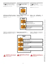
27 - ROTATION BLOCKING PIN CONTROL LEVER
This lever (27), on the RH of the operator,
controls the pin which blocks the hydraulic
rotation of the forklift truck.
The lever has two positions:
- To insert the blocking pin, push the lever
in position (A).
- To deactivate the blocking pin pull the
lever backwards in position (B).
(See image 25).
Before inserting the pin in its seat
to block the rotation, check to
make sure the upper part of the
forklift truck (turret) is aligned
by means of indicator (C2). When
the pin is inserted indicator (C3).
indicates that the pin is in its
seat. It is important when using
the “Rotation” command to
check by means of indicator (C1).
For correct and optimum use of
this device, refer to paragraph
“USING THE ROTATION DEVICE”
(See Chapter 1-INSTRUCTIONS).
(See image 25)
If the turret is not aligned and it was
erroneously lowered the rotation
lock pin, the turret rotation
control by joystick is disabled.
To restore the turret rotation
control by joystick lift the turret
locking pin by pulling the lever
(27).
(See image 25)
25
B
A
27
C1
C2
C3
27 - LEVA COMANDO PERNO BLOCCO
ROTAZIONE
Questa leva (27) situata alla destra dell’ ope-
ratore comanda il perno che blocca la rota-
zione idraulica del carrello elevatore.
La leva ha due posizioni:
- Per inserire il perno di blocco spingere la
leva in posizione (A).
- Per disinserire il perno di blocco tirare la
leva indietro in posizione (B).
(Vedi immagine 25).
Prima di inserire il perno
nella sede per bloccare la
rotazione, verifi
care che la
parte superiore del carrello
(torretta) sia allineata tramite
la spia (C2). Una volta inserito
il perno la spia (C3) segnala la
presenza del perno nella sede. È
importante al momento di usare
il comando della “Rotazione” di
verifi care tramite la spia (C1).
Per un corretto e migliore
utilizzo di questo dispositivo
fare riferimento al paragrafo
“UTILIZZO DEL DISPOSITIVO
DI ROTAZIONE” (Vedi Capitolo
1-ISTRUZIONI).
(Vedi immagine 25)
Se la torretta non è allineata ed
è stato erroneamente abbassato
il perno di blocco rotazione, il
comando di rotazione torretta
da joystick viene disabilitato.
Per ripristinare il comando di
rotazione torretta da joystick
sollevare il perno di blocco
torretta tirando la leva (27).
(Vedi immagine. 25)
27 - BEDIENHEBEL SPERRBOLZEN FÜR
ROTATION
Dieser Hebel (27), der sich rechts vom Fah-
rer befi ndet, steuert den Bolzen, der die
hydraulische Drehung des Laders blockiert.
Der Hebel hat zwei Positionen:
- Zum Einführen des Sperrbolzens, den
Hebel in die Position (A) schieben.
- Zum Herausziehen des Sperrbolzens,
den Hebel in die Position (B) schieben.
(Siehe Abbildung 25).
Bevor man den Bolzen in seine
Aufnahme steckt, um die Drehung
zu sperren, mit der Kontrollleuchte
(C2) sicherstellen, dass der obere
Teil des Unterwagens (Oberwagen)
ausgerichtet ist. Nachdem
der Bolzen eingeführt wurde,
meldet die Kontrollleuchte (C3)
die Präsenz des Bolzens in der
Aufnahme. Bei der Anwendung
des Bedienelements ist es wichtig,
mithilfe der Kontrollleuchte
(C1) das Bedienelement für
die "Drehung" zu überprüfen.
Für eine korrekte und bessere
Benutzung dieser Einrichtung wird
auf den Abschnitt “BENUTZUNG DER
DREHEINRICHTUNG” verwiesen
(siehe Kapitel 1-ANLEITUNGEN).
(Siehe Abbildung 25)
Wenn der Oberwagen nicht
ausgerichtet ist und der
Rotationszapfen für die Sperre
versehentlich abgesenkt wurde,
wird das Bedienelement zur
Drehung des Oberwagens
per Joystick deaktiviert.
Um das Bedienelement für die
Oberwagendrehung am Joystick
rückzusetzen, den Hebel (27)
ziehen und den Sperrbolzen des
Oberwagens heben.
(Siehe Abbildung. 25)
649050
IT-EN-DE
(01/06/2017)
MRT
EASY
55P
400
ST4
S2,
MRT
EASY
55P
360
ST4
S2,
MRT
EASY
75P
400
ST3B
S2,
MRT
EASY
75P
360
ST3B
S2,
MRT-X
EASY
75P
400
ST3A
S2,
MRT-X
EASY
75P
360
ST3A
S2