


2-94
IT
EN
DE
12V
°C
hours
STOP
22
24
25
26
A
B
C
24
23
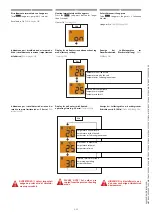
24 - FUNCTIONS CHARTS
These charts contain the description of
the hydraulic commands and the load
diagrams of the attachments included in
the forklift truck supply.
(See image 22).
25 - OPTIONAL EXCLUSION COMMAND
SWITCH
Switch “25”
(See image 23).
enables and disables
the control of the optional roller “1” (rope
ascent/descent) on servo-control “1.2”.
(See
image 21, page 60).
The attachment can be used only after enabling
the optional command.
26 - ATTACHMENTS AND PLATFORMS
MOVEMENTS SELECTOR
Select the function of the roller on the
servo-control “
1.2
” (LH).
(See image 21, page 64).
When the selector is in position
A
(See image
24).
the roller of the servo-control “
1.2
” (LH)
controls a hydraulic attachment, if any (if
present).
If the attachment has more than one
hydraulic movement, press the selector in
B
or in
C
.
(See image 24).
24 - SCHEDE FUNZIONI
Queste schede contengono la descrizione
dei comandi idraulici e i diagrammi di carico
degli accessori in dotazione al carrello
elevatore.
(Vedi immagine 22).
25 - INTERRUTTORE COMANDO ESCLUSIONE
OPTIONAL
L’interruttore “25”
(Vedi immagine 23).
abilita e
disabilita il comando di optional roller “1”
(salita /discesa fune) sul servocomando
“1.2”.
(Vedi immagine 21, pagina 60).
Solo dopo avere abilitato il comando optional
è possibile l’utilizzo del accessorio.
26 -
SELETTORE MOVIMENTI ACCESSORI E
CESTELLI
Seleziona la funzione del roller sul
servocomando “
1.2
” (SINISTRO).
(Vedi immagine 21, pagina 64).
Quando il selettore è in posizione
A
(Vedi
immagine 24).
il roller del servocomando
“
1.2
” (SINISTRO) comanda un eventuale
accessorio idraulico (se presente).
Se l’accessorio ha più di un movimento
idraulico premere il selettore in
B
o in
C
.
(Vedi immagine 24).
24 - DATENBLÄTTER DER FUNKTIONEN
Diese Datenblätter beinhalten die
Beschreibung der hydraulischen
Bedienelemente sowie die Lastdiagramme
der Anbaugeräte, die zur Ausrüstung des
Teleskopladers gehören.
(Siehe Abbildung 22).
25 - AUSSCHLUSSSCHALTER OPTIONAL
Der Schalter “25”
(Siehe Abbildung 23).
aktiviert
oder deaktiviert das Bedienelement des
Optionals Roller "1" (Auf-/Abbewegung des
Seils) auf der Servosteuerung “1.2”.
(Siehe
Abbildung 21, Seite 60).
Das Anbaugerät kann nur nach Freigabe des
optionalen Bedienelements benutzt werden.
26 - WÄHLSCHALTER
BEWEGUNGEN
ANBAUGERÄTE UND KÖRBE
Wählt die Funktion des Rollers auf der
Servosteuerung “
1.2
” (LINKS).
(Siehe Abbildung 21, Seite 64).
Wenn der Wählschalter in der Stellung
A
(Siehe Abbildung 24)
ist, steuert der Roller der
Servosteuerung “
1.2
” (LINKS) ein eventuell
vorhandenes hydraulisches Anbaugerät
(falls vorhanden).
Wenn das Anbaugerät mehr als eine
Hydraulikbewegung ausführen kann, den
Wählschalter auf
B
oder
C
drücken.
(Siehe Abbildung 24).
649050
IT-EN-DE
(01/06/2017)
MRT
EASY
55P
400
ST4
S2,
MRT
EASY
55P
360
ST4
S2,
MRT
EASY
75P
400
ST3B
S2,
MRT
EASY
75P
360
ST3B
S2,
MRT-X
EASY
75P
400
ST3A
S2,
MRT-X
EASY
75P
360
ST3A
S2