Appendix D
© 2018 Avco Corporation. All Rights Reserved
Page 434
November 2018
TEO-540-C1A Engine Maintenance Manual
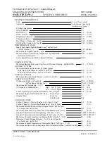
Fault ID
151
Fault Group
19
Fault Name
[FAULT: manifold pressure slew
rate]
Fault
Description
Manifold Pressure slew rate fault
Fault Lamp
None
Root Cause
This fault indicates the pressure sensor slew rate is greater than the calibrated maximum.
Troubleshooting Steps
1.
Run the engine in accordance with the engine and aircraft maintenance manuals. Is the fault active? *
If yes, go to step 3. If no, go to step 2.
2.
Using the FST, download active and service fault logs, then clear fault logs and monitor engine
operation for the fault to repeat.
3.
Inspect sensor, and lines for any damage (eg…burned, broken or frayed wires, cracked or broken
connectors or hoses, burned or broken sensors). If damaged, replace the sensor per the “Sensor
Replacement Procedures” section in Chapter 72-70. If no damage is found, go to step 4.
4.
Inspect harness connection for any damage (eg…burned, broken or frayed wires, cracked or broken
connectors). Contact Lycoming if harness damage is found. If no damage found, go to step 5.
5.
Complete a continuity test of the harness from the harness sensor connector to the ECU connector using
the engine system schematic. If the continuity check fails, isolate to affected harness by disconnecting
the firewall connection, then contact Lycoming Engines. If the continuity checks good, replace the
sensor. If fault persists, replace the ECU.
*NOTE: This fault could be caused by another manifold pressure fault. If there are any other active
manifold pressure faults go to troubleshooting steps for the corresponding manifold pressure fault.
Fault ID
152
Fault Group
20
Fault Name
[FAULT: local deck pressure slew
rate]
Fault
Description
Local Deck Pressure slew rate fault
Fault Lamp
None
Root Cause
This fault indicates the pressure sensor slew rate is greater than the calibrated maximum.
Troubleshooting Steps
1.
Run the engine in accordance with the engine and aircraft maintenance manuals. Is the fault active? *
If yes, go to step 3. If no, go to step 2.
2.
Using the FST, download active and service fault logs, then clear fault logs and monitor engine
operation for the fault to repeat.
3.
Inspect sensor, and lines for any damage (eg…burned, broken or frayed wires, cracked or broken
connectors or hoses, burned or broken sensors). If damaged, replace the sensor per the “Sensor
Replacement Procedures” section in Chapter 72-70. If no damage is found, go to step 4.
4.
Inspect harness connection for any damage (eg…burned, broken or frayed wires, cracked or broken
connectors). Contact Lycoming if harness damage is found. If no damage found, go to step 5.
5.
Swap affected sensor ((A036 or A045) with opposite sensor. Run the engine. Does the fault move with
the sensor? If yes, replace the sensor. If no, go to step 6.
6.
Complete a continuity test of the harness from the harness sensor connector to the ECU connector using
the engine system schematic. If the continuity check fails, isolate to affected harness by disconnecting
the firewall connection, then contact Lycoming Engines. If the continuity checks good, replace the
sensor. If fault persists, replace the ECU.
*NOTE: This fault could be caused by another deck pressure fault. If there are any other active deck
pressure faults go to troubleshooting steps for the corresponding deck pressure fault.