Appendix D
© 2018 Avco Corporation. All Rights Reserved
Page 526
November 2018
TEO-540-C1A Engine Maintenance Manual
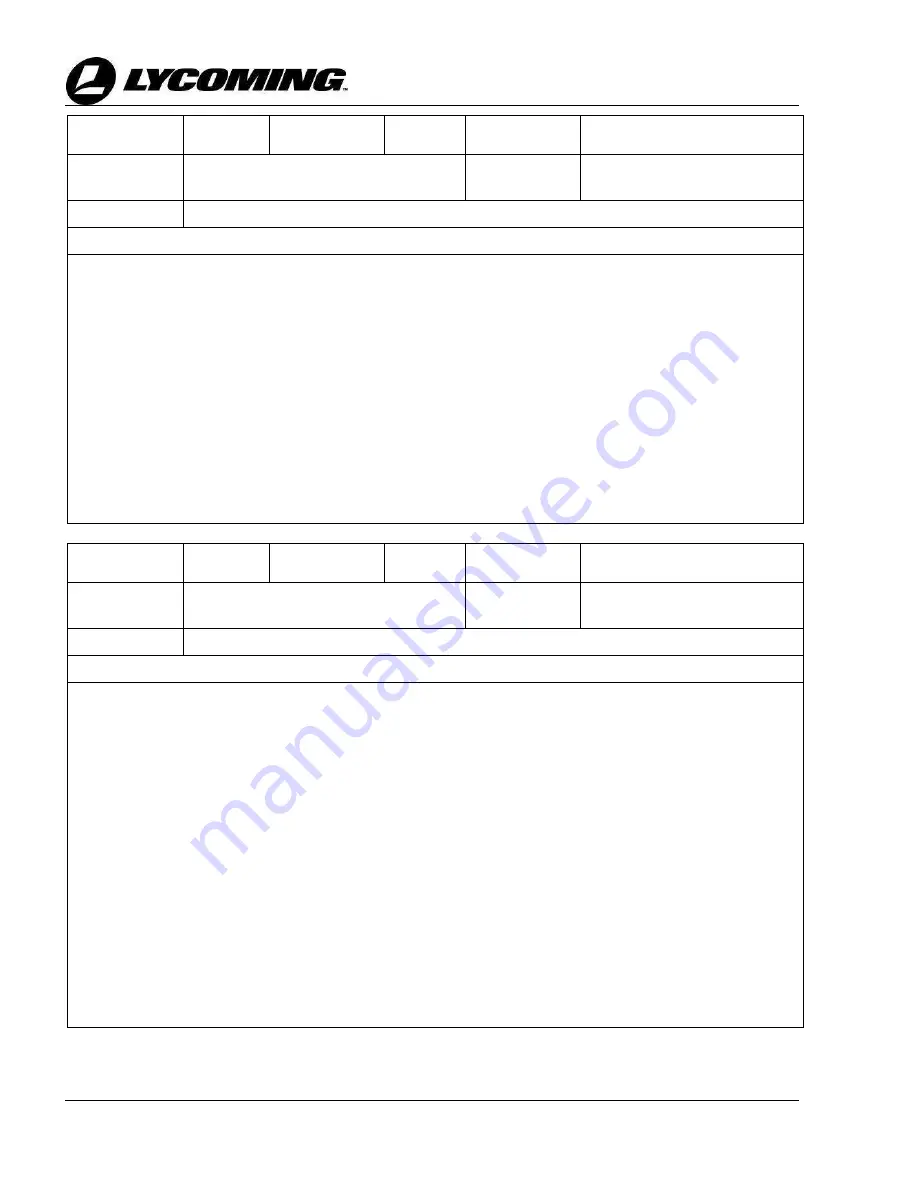
Fault ID
472
Fault Group
60
Fault Name
[FAULT: data logger message
watchdog]
Fault
Description
Data logger message watchdog fault
Fault Lamp
None
Root Cause
This fault indicates a failure transmitting messages to the data logger
Troubleshooting Steps
1.
Is fault active or logged? If yes, go to step 2. If no, go to step 5.
2.
With Ignition switch in OFF position, remove ECU power by pulling the ECU circuit breaker. Wait 10s
before resetting. Is fault still active? If yes, go to step 3. If no, go to step 5.
3.
Inspect the data logger and cabling for damage. If damage is noted, repair damage in accordance with
aircraft maintenance manual. If data logger is damage, replace. If no damage noted, go to step 4.
4.
Complete a continuity test of the harness from the data logger connector to the ECU connector using the
engine system schematic in Appendix B and airframe wiring manual. If the continuity check fails,
isolate to affected harness by disconnecting the airframe interface connection AF-P1. If the continuity
fails between the data logger and AF-J1, repair the cable in accordance with aircraft maintenance
manual. If the continuity fails between AF-P1 and ECU, contact Lycoming Engines. If the continuity
checks good, replace the data logger.
5.
Clear Service faults using the FST by following the steps outlined in the “Access the Field Service
Tool” section in Appendix C or the latest revision of
SSP-118.
Fault ID
473
Fault Group
60
Fault Name
[FAULT: instrumentation message
watchdog]
Fault
Description
Instrumentation message watchdog
fault
Fault Lamp
None
Root Cause
This fault indicates a failure with CAN messages on the instrumentation interface
Troubleshooting Steps
1.
With Ignition switch in OFF position, remove ECU power by pulling the ECU circuit breaker. Wait 10s
before resetting. Is fault still active? If yes, go to step 2. If no, go to step 5.
2.
Turn ignition switch ON. Is engine instrumentation display showing all active engine parameters
correctly? If no, go to step 3. If yes, go to step 4.
3.
Complete an engine instrumentation display self-test in accordance with the aircraft maintenance
manual or display manufacturer’s instructions (if equipped). Did self-test pass? If yes, go to step 4. If
no, replace display, then go to step 5.
4.
Complete a continuity and short circuit test of the harness from the aircraft engine instrument display
connector to ECU connector using the engine system schematic in Appendix B and aircraft wiring
diagram. If the continuity or short circuit check fails, isolate to affected harness by disconnecting the
airframe interface connection AF-P1. If problem is isolated to engine airframe harness, contact
Lycoming Engines. If problem is found from aircraft engine instrument display connector to AF-J1,
repair in accordance with the aircraft maintenance manual. If the continuity check is good, using
aircraft maintenance manual, and serviceability of the aircraft engine instrument display has been
verified, replace the ECU.
5.
Clear Service faults using the FST by following the steps outlined in the “Access the Field Service
Tool” section in Appendix C or the latest revision of
SSP-118.