391
RS-485 Communication Features
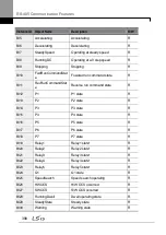
Group Code Name
LCD display
Parameter
Setting
Setting Range Unit
2 D8/PE/S1
3 D8/PO/S1
20
Maximum number
of BACnet
Masters
BAC Max
Master
0
0–127
-
21
BACnet device
number 1
BAC Dev
Inst1
237
0–4149
-
22
BACnet device
number 2
BAC Dev
Inst1
0
0–999
-
23
BACnet device
password
BAC
PassWord
0
0–32767
-
1) 1200 bps, 2400 bps, 4800 bps, 57600 bps, 115200 bps cannot be set in communication
speed setting in case of BACnet communication.
BACnet Parameter Setting Details
Code
Description
COM-01 Int485
ST ID(MAC ID)
Refers to MACID setting parameter used in BACnet. All MACIDs of the
inverter using BACnet must be set before connecting to BUS. MACID must
have the unique value from the Network to be connected to MACID. If
BACnet is used, the value must be within 0–127. Communication is not
available if the value is not included in the range.
COM-03 Baud
Rate
Sets the communication speed to use in the network.
COM-20 BAC
Mas Master
Range for Max Master that is the number of devices currently connected to
the communication Line is 1–127, and the default value is 127.
COM-21–22
BAC Dev Inst 1–
2
BACnet Device Instance is used to identify BACnet Device, and must be
set as the unique value in the BACnet network. It is used efficiently when
finding BACnet Device of other Devices while installing.
The following formula is used to calculate the Device Instance value:
(COM-21 X 1000) + COM-22
Therefore, in the Device Instance value, COM-21 takes the thousands and
higher places (fourth digit and over) and COM-22 takes the hundreds and
lower places (third digit and below).
COM-21 and COM-22 have the ranges of 0–4194 and 0–999 respectively,
because Device Instance can have the value within 0–4,194,302.
COM-23 BAC
Refers to the password used for Warm/Cold Start. COM-23 Password
Содержание LSLV0055H100-4COFN
Страница 14: ......
Страница 18: ...Preparing the Installation 4 37 90 kW 3 Phase ...
Страница 27: ...Preparing the Installation 13 ...
Страница 47: ...33 Installing the Inverter ...
Страница 48: ...Installing the Inverter 34 Input and Output Control Terminal Block Wiring Diagram ...
Страница 61: ...47 Installing the Inverter ...
Страница 71: ...Learning to Perform Basic Operations 57 ...
Страница 88: ...Learning to Perform Basic Operations 74 ...
Страница 103: ...89 Learning Basic Features Code Description V1 Quantizing ...
Страница 120: ...Learning Basic Features 106 Grou p Cod e Name LCD Display Parameter Setting Setting Range Unit Prev ...
Страница 129: ...115 Learning Basic Features ...
Страница 140: ...Learning Basic Features 126 ...
Страница 148: ...Learning Basic Features 134 ...
Страница 171: ...157 Learning Advanced Features Deceleration dwell operation ...
Страница 183: ...169 Learning Advanced Features ...
Страница 184: ...Learning Advanced Features 170 PID Command Block ...
Страница 185: ...171 Learning Advanced Features PID Feedback Block ...
Страница 186: ...Learning Advanced Features 172 PID Output Block ...
Страница 187: ...173 Learning Advanced Features PID Output Mode Block ...
Страница 197: ...183 Learning Advanced Features ...
Страница 201: ...187 Learning Advanced Features Code Description 100 EPID1 Control block ...
Страница 202: ...Learning Advanced Features 188 EPID2 Control block ...
Страница 237: ...223 Learning Advanced Features Time Period Schedule AP3 38 Except3 Day 01 01 ...
Страница 244: ...Learning Advanced Features 230 ...
Страница 259: ...245 Learning Advanced Features Code Description Code Description Volt ...
Страница 362: ...Learning Protection Features 348 ...
Страница 415: ...401 RS 485 Communication Features Item Standards Parity check None ...
Страница 524: ...Table of Functions 510 ...
Страница 533: ...Table of Functions 519 ...
Страница 547: ...533 Troubleshooting ...
Страница 564: ...Technical Specification 550 11 3 External Dimensions IP 20 Type 0 75 30 kW 3 phase 37 90 kW 3 phase ...
Страница 585: ...Technical Specification 571 ...
Страница 594: ...580 ...
Страница 595: ...581 ...
Страница 596: ...582 ...


