


Learning Advanced Features
176
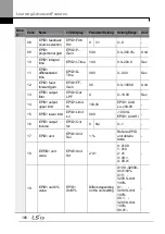
5.8.3 PID Sleep Mode
If an operation continues at a frequency lower than the PID operation conditions, a boost
operation is performed to extend sleep mode by raising the PID Reference, and then the
inverter enters PID sleep mode. In PID sleep mode, the inverter resumes PID operation
when the PID feedback falls below the PID Wakeup level and maintains the condition for
the time set at AP1-09 (PID WakeUp1 DT) or AP1-13 (PID WakeUp2DT).
Note
PID Wakeup level may be calculated using the following formula:
PID Wakeup Level = PID-04 (PID Ref Value)–AP1-10 (PID WakeUp1Dev) or, PID-04 (PID Ref
Value) - AP1-14 PID (WakeUp2Dev).
Two sets of configurations are available in PID sleep mode for sleep mode frequency, sleep
mode delay time, wakeup variation, and wakeup delay time. One of the two configurations
may be selected depending on the multi-function input terminal configuration and input
conditions.
Group Code Name
LCD Displays Parameter Setting Setting
Range
Unit
AP1
05
Sleep boost settings Sleep Bst Set 0.00
0–Unit Max
Unit
06
Sleep boost speed Sleep Bst
Freq
60.00
0.00, Low
Freq–High
Freq
Hz
07
PID sleep mode 1
delay time
PID Sleep 1
DT
20.0
0–6000.0
sec
08
PID sleep mode 1
frequency
PID
Sleep1Freq
0.00
0.00, Low
Freq–High
Freq
Hz
09
PID wakeup 1 delay
time
PID
WakeUp1 DT 20.0
0–6000.0
sec
10
PID wakeup 1 value PID
WakeUp1Dev 20.00
0–Unit Band Unit
11
PID sleep mode 2
delay time
PID Sleep 2
DT
20.0
0–6000.0
sec
12
PID sleep mode 2
frequency
PID
Sleep2Freq
0.00
0.00, Low
Freq–High
Freq
Hz
13
PID wakeup 2 delay
time
PID
WakeUp2 DT 20.0
0–6000.0
sec
Содержание LSLV0055H100-4COFN
Страница 14: ......
Страница 18: ...Preparing the Installation 4 37 90 kW 3 Phase ...
Страница 27: ...Preparing the Installation 13 ...
Страница 47: ...33 Installing the Inverter ...
Страница 48: ...Installing the Inverter 34 Input and Output Control Terminal Block Wiring Diagram ...
Страница 61: ...47 Installing the Inverter ...
Страница 71: ...Learning to Perform Basic Operations 57 ...
Страница 88: ...Learning to Perform Basic Operations 74 ...
Страница 103: ...89 Learning Basic Features Code Description V1 Quantizing ...
Страница 120: ...Learning Basic Features 106 Grou p Cod e Name LCD Display Parameter Setting Setting Range Unit Prev ...
Страница 129: ...115 Learning Basic Features ...
Страница 140: ...Learning Basic Features 126 ...
Страница 148: ...Learning Basic Features 134 ...
Страница 171: ...157 Learning Advanced Features Deceleration dwell operation ...
Страница 183: ...169 Learning Advanced Features ...
Страница 184: ...Learning Advanced Features 170 PID Command Block ...
Страница 185: ...171 Learning Advanced Features PID Feedback Block ...
Страница 186: ...Learning Advanced Features 172 PID Output Block ...
Страница 187: ...173 Learning Advanced Features PID Output Mode Block ...
Страница 197: ...183 Learning Advanced Features ...
Страница 201: ...187 Learning Advanced Features Code Description 100 EPID1 Control block ...
Страница 202: ...Learning Advanced Features 188 EPID2 Control block ...
Страница 237: ...223 Learning Advanced Features Time Period Schedule AP3 38 Except3 Day 01 01 ...
Страница 244: ...Learning Advanced Features 230 ...
Страница 259: ...245 Learning Advanced Features Code Description Code Description Volt ...
Страница 362: ...Learning Protection Features 348 ...
Страница 415: ...401 RS 485 Communication Features Item Standards Parity check None ...
Страница 524: ...Table of Functions 510 ...
Страница 533: ...Table of Functions 519 ...
Страница 547: ...533 Troubleshooting ...
Страница 564: ...Technical Specification 550 11 3 External Dimensions IP 20 Type 0 75 30 kW 3 phase 37 90 kW 3 phase ...
Страница 585: ...Technical Specification 571 ...
Страница 594: ...580 ...
Страница 595: ...581 ...
Страница 596: ...582 ...


