307
Learning Advanced Features
Code
Description
4
FDT-4
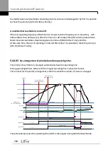
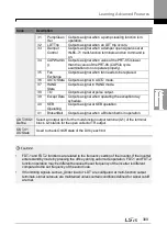
The output signal can be separately set for acceleration
and deceleration conditions.
•
In acceleration:
Operation frequency
≧
Detected
frequency
•
In deceleration:
Operation frequency > (Detected
frequency–Detected frequency width/2)
Detected frequency width is 10 Hz. When the detected
frequency is set to 30 Hz, FDT-4 output is as shown in
the graph below.
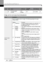
5
Over Load
Outputs a signal at motor overload.
6
IOL
Outputs a signal when the inverter input current
exceeds the rated current and a protective function is
activated to prevent damage to the inverter, based on
inverse proportional characteristics.
7
Under Load Outputs a signal at load fault warning.
8
Fan
Warning
Outputs a signal at fan fault warning.
9
Stall
Outputs a signal when a motor is overloaded and
stalled.
10
Over
Voltage
Outputs a signal when the inverter DC link voltage rises
above the protective operation voltage.
11
Low Voltage Outputs a signal when the inverter DC link voltage
drops below the low voltage protective level.
12
Over Heat
Outputs signal when the inverter overheats.
13
Lost
Command
Outputs a signal when there is a loss of analog input
terminal and RS-485 communication command at the
terminal block.
Outputs a signal when communication power is present
and an I/O expansion card is installed. It also outputs a
signal when losing analog input and communication
power commands.
14
RUN
Outputs a signal when an operation command is
entered and the inverter outputs voltage.
No signal output during DC braking.
Содержание LSLV0055H100-4COFN
Страница 14: ......
Страница 18: ...Preparing the Installation 4 37 90 kW 3 Phase ...
Страница 27: ...Preparing the Installation 13 ...
Страница 47: ...33 Installing the Inverter ...
Страница 48: ...Installing the Inverter 34 Input and Output Control Terminal Block Wiring Diagram ...
Страница 61: ...47 Installing the Inverter ...
Страница 71: ...Learning to Perform Basic Operations 57 ...
Страница 88: ...Learning to Perform Basic Operations 74 ...
Страница 103: ...89 Learning Basic Features Code Description V1 Quantizing ...
Страница 120: ...Learning Basic Features 106 Grou p Cod e Name LCD Display Parameter Setting Setting Range Unit Prev ...
Страница 129: ...115 Learning Basic Features ...
Страница 140: ...Learning Basic Features 126 ...
Страница 148: ...Learning Basic Features 134 ...
Страница 171: ...157 Learning Advanced Features Deceleration dwell operation ...
Страница 183: ...169 Learning Advanced Features ...
Страница 184: ...Learning Advanced Features 170 PID Command Block ...
Страница 185: ...171 Learning Advanced Features PID Feedback Block ...
Страница 186: ...Learning Advanced Features 172 PID Output Block ...
Страница 187: ...173 Learning Advanced Features PID Output Mode Block ...
Страница 197: ...183 Learning Advanced Features ...
Страница 201: ...187 Learning Advanced Features Code Description 100 EPID1 Control block ...
Страница 202: ...Learning Advanced Features 188 EPID2 Control block ...
Страница 237: ...223 Learning Advanced Features Time Period Schedule AP3 38 Except3 Day 01 01 ...
Страница 244: ...Learning Advanced Features 230 ...
Страница 259: ...245 Learning Advanced Features Code Description Code Description Volt ...
Страница 362: ...Learning Protection Features 348 ...
Страница 415: ...401 RS 485 Communication Features Item Standards Parity check None ...
Страница 524: ...Table of Functions 510 ...
Страница 533: ...Table of Functions 519 ...
Страница 547: ...533 Troubleshooting ...
Страница 564: ...Technical Specification 550 11 3 External Dimensions IP 20 Type 0 75 30 kW 3 phase 37 90 kW 3 phase ...
Страница 585: ...Technical Specification 571 ...
Страница 594: ...580 ...
Страница 595: ...581 ...
Страница 596: ...582 ...


