


277
Learning Advanced Features
AP1-61
AP1-62
AP1-63
AP1-64
AP1-65
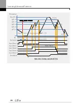
Max Freq
Inverter
Out Freq
AP1-70
AP1-71
AP1-72
Aux Motor 1
Aux Motor 2
Aux Motor 3
Aux Motor 4
Aux Motor 5
Feedback
AP1-70
AP1-71
AP1-72
Perform Aux_Exch
Reset the [Auto Op Time]
AP1-62
AP1-63
AP1-64
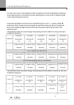
0%
100%
Fx
Off
On
Priority of the moment
M2
M1
M3 /
M4
M5
Priority of the moment
M1
M2
M3 /
M4
M5
Priority of the moment
M3
M2
M1 /
M4
M5
Priority of the moment
M3
M2
M1 /
M4
M5
5min
10min
AP1-61
Priority of the moment
M4
M5
M3 /
M2
M1
30min
Operation time
M1(30min) / M2(25min) /
M3(20min)
AP1-73
Priority of the moment
M4
M5
M3 /
M2
M1
Motor to operate MMC : M1, M2, M3
Standby motor : M4, M5
Motor to operate MMC : M3, M4, M5
Standby motor : M1, M2
Supposing its operation in
less than 1 minute
AP1-74
AP1-72
AP1-65
Aux Auto Change
operation
(Op Time Order)
when operable motor and standby motor are set to 3 and 2 each
Option 1: [AP1-58 Auto Op Time] >= [AP1-56: Auto Ch Time]
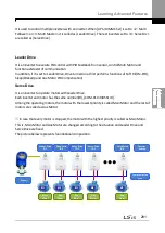
When
AP1-55 (Auto Ch Mode) is set to ‗2
(Main Exchange),‘ the system uses all the motors
(main and auxiliary motors) regardless of the types. The auxiliary motor with the highest
priority is operated first and used as the main motor. Then, when the auto change
conditions are met, this motor is stopped and the motor priorities are re-arranged. This way,
the system always operates the motor with the highest priority and uses it as the main
motor of the MMC operation. In this case, before auto change is operated for the main
motor, the interlock delay time set at AP1-91 (Interlock DT) is applied.
Содержание LSLV0055H100-4COFN
Страница 14: ......
Страница 18: ...Preparing the Installation 4 37 90 kW 3 Phase ...
Страница 27: ...Preparing the Installation 13 ...
Страница 47: ...33 Installing the Inverter ...
Страница 48: ...Installing the Inverter 34 Input and Output Control Terminal Block Wiring Diagram ...
Страница 61: ...47 Installing the Inverter ...
Страница 71: ...Learning to Perform Basic Operations 57 ...
Страница 88: ...Learning to Perform Basic Operations 74 ...
Страница 103: ...89 Learning Basic Features Code Description V1 Quantizing ...
Страница 120: ...Learning Basic Features 106 Grou p Cod e Name LCD Display Parameter Setting Setting Range Unit Prev ...
Страница 129: ...115 Learning Basic Features ...
Страница 140: ...Learning Basic Features 126 ...
Страница 148: ...Learning Basic Features 134 ...
Страница 171: ...157 Learning Advanced Features Deceleration dwell operation ...
Страница 183: ...169 Learning Advanced Features ...
Страница 184: ...Learning Advanced Features 170 PID Command Block ...
Страница 185: ...171 Learning Advanced Features PID Feedback Block ...
Страница 186: ...Learning Advanced Features 172 PID Output Block ...
Страница 187: ...173 Learning Advanced Features PID Output Mode Block ...
Страница 197: ...183 Learning Advanced Features ...
Страница 201: ...187 Learning Advanced Features Code Description 100 EPID1 Control block ...
Страница 202: ...Learning Advanced Features 188 EPID2 Control block ...
Страница 237: ...223 Learning Advanced Features Time Period Schedule AP3 38 Except3 Day 01 01 ...
Страница 244: ...Learning Advanced Features 230 ...
Страница 259: ...245 Learning Advanced Features Code Description Code Description Volt ...
Страница 362: ...Learning Protection Features 348 ...
Страница 415: ...401 RS 485 Communication Features Item Standards Parity check None ...
Страница 524: ...Table of Functions 510 ...
Страница 533: ...Table of Functions 519 ...
Страница 547: ...533 Troubleshooting ...
Страница 564: ...Technical Specification 550 11 3 External Dimensions IP 20 Type 0 75 30 kW 3 phase 37 90 kW 3 phase ...
Страница 585: ...Technical Specification 571 ...
Страница 594: ...580 ...
Страница 595: ...581 ...
Страница 596: ...582 ...


