


Learning Advanced Features
308
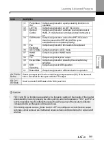
Code
Description
15
Stop
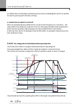
Outputs a signal at operation command off, and when
there is no inverter output voltage.
16
Steady
Outputs a signal in steady operation.
17
Inverter
Line
Outputs a signal while the motor is driven by the
inverter line.
18
Comm Line Outputs a signal when multi-function input terminal
(switching) is entered. For details, refer to
19
Speed
Search
Outputs a signal during inverter speed search
operation.
For details, refer to
on
20
Ready
Outputs a signal when the inverter is in stand by mode
and ready to receive external operation commands.
21
MMC
Used as a multi-motor control function. By configuring
the relay output and the multi-function output to MMC
and configuring the AP1-40–AP1-92, it can conduct the
necessary operations for multi-motor control function.
22
Timer Out
A timer function to operate terminal output after a
certain time by using multi-function terminal block input.
For details, refer to 5.43
on page 259.
23
Trip
Outputs a signal after a fault trip.
Refer to 5.45 Multi-function Output On/Off Control on
page 259 .
25
DB
Warn %ED
Refer to 0
Dynamic Braking (DB) Resistor Configuration on page
295.
26
On/Off
Control
Outputs a signal using an analog input value as a
standard.
Refer to 5.45 Multi-function Output On/Off Control on
page 259 .
27 Fire Mode
Outputs a signal when Fire mode is in operation.
28
Pipe Break Outputs a signal when a pipe is broken.
29
Damper Err Outputs a signal when damper open signal is not
entered. For more details, refer to 0
30
Lubrication Outputs a signal when a lubrication function is in
operation.
Содержание LSLV0055H100-4COFN
Страница 14: ......
Страница 18: ...Preparing the Installation 4 37 90 kW 3 Phase ...
Страница 27: ...Preparing the Installation 13 ...
Страница 47: ...33 Installing the Inverter ...
Страница 48: ...Installing the Inverter 34 Input and Output Control Terminal Block Wiring Diagram ...
Страница 61: ...47 Installing the Inverter ...
Страница 71: ...Learning to Perform Basic Operations 57 ...
Страница 88: ...Learning to Perform Basic Operations 74 ...
Страница 103: ...89 Learning Basic Features Code Description V1 Quantizing ...
Страница 120: ...Learning Basic Features 106 Grou p Cod e Name LCD Display Parameter Setting Setting Range Unit Prev ...
Страница 129: ...115 Learning Basic Features ...
Страница 140: ...Learning Basic Features 126 ...
Страница 148: ...Learning Basic Features 134 ...
Страница 171: ...157 Learning Advanced Features Deceleration dwell operation ...
Страница 183: ...169 Learning Advanced Features ...
Страница 184: ...Learning Advanced Features 170 PID Command Block ...
Страница 185: ...171 Learning Advanced Features PID Feedback Block ...
Страница 186: ...Learning Advanced Features 172 PID Output Block ...
Страница 187: ...173 Learning Advanced Features PID Output Mode Block ...
Страница 197: ...183 Learning Advanced Features ...
Страница 201: ...187 Learning Advanced Features Code Description 100 EPID1 Control block ...
Страница 202: ...Learning Advanced Features 188 EPID2 Control block ...
Страница 237: ...223 Learning Advanced Features Time Period Schedule AP3 38 Except3 Day 01 01 ...
Страница 244: ...Learning Advanced Features 230 ...
Страница 259: ...245 Learning Advanced Features Code Description Code Description Volt ...
Страница 362: ...Learning Protection Features 348 ...
Страница 415: ...401 RS 485 Communication Features Item Standards Parity check None ...
Страница 524: ...Table of Functions 510 ...
Страница 533: ...Table of Functions 519 ...
Страница 547: ...533 Troubleshooting ...
Страница 564: ...Technical Specification 550 11 3 External Dimensions IP 20 Type 0 75 30 kW 3 phase 37 90 kW 3 phase ...
Страница 585: ...Technical Specification 571 ...
Страница 594: ...580 ...
Страница 595: ...581 ...
Страница 596: ...582 ...


