


319
Learning Protection Features
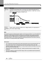
To operate the motor overheat protection, connect the overheat protection temperature
sensor (PT 100, PTC) installed in the motor to the inverter‘s analog input terminal.
Group Code Name
LCD Display
Parameter
Setting
Setting
Range
Unit
PRT
34
Selecting the operation
after the detection of the
motor overheat
detection sensor
Thermal-T Sel 0
None
0–1
-
35
Selecting the input of
the motor overheat
detection sensor
Thermal In Src 0
Thermal
In
0–1
36
Fault level of the motor
overheat detection
sensor
Thermal-T Lev 50.0
0.0–
100.0
%
37
Fault area of the motor
overheat detection
sensor
Thermal-T
Area
0
Low
0–1
OUT
07
Analog output 2 item
AO2 Mode
14 Constant 0–18
08
Analog output 2 gain
AO2 Gain
100
0–100
%
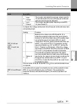
Motor Overheat Protect Sensor Input Detail Settings
Code
Description
PRT-34
Thermal-T Sel
Sets the inverter operation state when motor is overheated.
Setting
Function
0 None
Do not operate when motor overheating is detected.
1 Free-Run
When the motor is overheated, the inverter output is
blocked and the motor will free-run by inertia.
3 Dec
When the motor is over heated, the motor
decelerates and stops.
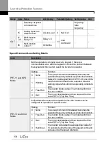
PRT-35
Thermal In Src
Selects the type of the terminal when the motor overheat protect sensor is
connected to the volt (V1) or current (I2) input terminal of the terminal
block in the inverter.
Setting
Function
0 Thermal In Configure the motor overheat protect sensor
connection to terminal block V1.
1 V2
Configure the motor overheat protect sensor
Содержание LSLV0055H100-4COFN
Страница 14: ......
Страница 18: ...Preparing the Installation 4 37 90 kW 3 Phase ...
Страница 27: ...Preparing the Installation 13 ...
Страница 47: ...33 Installing the Inverter ...
Страница 48: ...Installing the Inverter 34 Input and Output Control Terminal Block Wiring Diagram ...
Страница 61: ...47 Installing the Inverter ...
Страница 71: ...Learning to Perform Basic Operations 57 ...
Страница 88: ...Learning to Perform Basic Operations 74 ...
Страница 103: ...89 Learning Basic Features Code Description V1 Quantizing ...
Страница 120: ...Learning Basic Features 106 Grou p Cod e Name LCD Display Parameter Setting Setting Range Unit Prev ...
Страница 129: ...115 Learning Basic Features ...
Страница 140: ...Learning Basic Features 126 ...
Страница 148: ...Learning Basic Features 134 ...
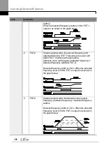
Страница 171: ...157 Learning Advanced Features Deceleration dwell operation ...
Страница 183: ...169 Learning Advanced Features ...
Страница 184: ...Learning Advanced Features 170 PID Command Block ...
Страница 185: ...171 Learning Advanced Features PID Feedback Block ...
Страница 186: ...Learning Advanced Features 172 PID Output Block ...
Страница 187: ...173 Learning Advanced Features PID Output Mode Block ...
Страница 197: ...183 Learning Advanced Features ...
Страница 201: ...187 Learning Advanced Features Code Description 100 EPID1 Control block ...
Страница 202: ...Learning Advanced Features 188 EPID2 Control block ...
Страница 237: ...223 Learning Advanced Features Time Period Schedule AP3 38 Except3 Day 01 01 ...
Страница 244: ...Learning Advanced Features 230 ...
Страница 259: ...245 Learning Advanced Features Code Description Code Description Volt ...
Страница 362: ...Learning Protection Features 348 ...
Страница 415: ...401 RS 485 Communication Features Item Standards Parity check None ...
Страница 524: ...Table of Functions 510 ...
Страница 533: ...Table of Functions 519 ...
Страница 547: ...533 Troubleshooting ...
Страница 564: ...Technical Specification 550 11 3 External Dimensions IP 20 Type 0 75 30 kW 3 phase 37 90 kW 3 phase ...
Страница 585: ...Technical Specification 571 ...
Страница 594: ...580 ...
Страница 595: ...581 ...
Страница 596: ...582 ...


