


Learning Advanced Features
310
5.48.2 Fault Trip Output using Multi-function Output Terminal and Relay
The inverter can output a fault trip state using the multi-function output terminal (Q1) and
relay (Relay 1).
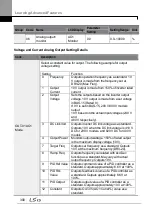
Group Code Name
LCD Display
Parameter
Setting
Setting
Range
Unit
OUT
30
Fault trip output mode Trip Out Mode 010
-
bit
31
Multi-function relay 1
Relay 1
23 Trip
-
-
32
Multi-function relay 2
Relay 2
14 Run
-
-
33
Multi-function relay 3
Relay 3
0 none
-
34
Multi-function relay 4
Relay 4
0 none
-
35
Multi-function relay 5
Relay 5
0 none
-
36
Multi-function output1 Q1 Define
0 none
-
-
53
Fault trip output on
delay
TripOut OnDly 0.00
0.00–100.00 sec
54
Fault trip output off
delay
TripOut OffDly 0.00
0.00–100.00 sec
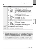
Fault Trip Output by Multi-function Output Terminal and Relay - Setting Details
Code
Description
OUT-30 Trip Out
Mode
Fault trip relay operates based on the fault trip output settings.
Item
bit on
bit off
Keypad
display
Select a fault trip output terminal/relay and select ‗29‘ (Trip Mode) at
codes OUT- 31–33. When a fault trip occurs in the inverter, the relevant
terminal and relay will operate. Depending on the fault trip type, terminal
and relay operation can be configured as shown in the table below.
Setting
Function
bit3
bit2
bit1
Operates when low voltage fault trips occur
Operates when fault trips other than low
voltage occur
Operates when auto restart fails (PRT-08–
09)
Содержание LSLV0055H100-4COFN
Страница 14: ......
Страница 18: ...Preparing the Installation 4 37 90 kW 3 Phase ...
Страница 27: ...Preparing the Installation 13 ...
Страница 47: ...33 Installing the Inverter ...
Страница 48: ...Installing the Inverter 34 Input and Output Control Terminal Block Wiring Diagram ...
Страница 61: ...47 Installing the Inverter ...
Страница 71: ...Learning to Perform Basic Operations 57 ...
Страница 88: ...Learning to Perform Basic Operations 74 ...
Страница 103: ...89 Learning Basic Features Code Description V1 Quantizing ...
Страница 120: ...Learning Basic Features 106 Grou p Cod e Name LCD Display Parameter Setting Setting Range Unit Prev ...
Страница 129: ...115 Learning Basic Features ...
Страница 140: ...Learning Basic Features 126 ...
Страница 148: ...Learning Basic Features 134 ...
Страница 171: ...157 Learning Advanced Features Deceleration dwell operation ...
Страница 183: ...169 Learning Advanced Features ...
Страница 184: ...Learning Advanced Features 170 PID Command Block ...
Страница 185: ...171 Learning Advanced Features PID Feedback Block ...
Страница 186: ...Learning Advanced Features 172 PID Output Block ...
Страница 187: ...173 Learning Advanced Features PID Output Mode Block ...
Страница 197: ...183 Learning Advanced Features ...
Страница 201: ...187 Learning Advanced Features Code Description 100 EPID1 Control block ...
Страница 202: ...Learning Advanced Features 188 EPID2 Control block ...
Страница 237: ...223 Learning Advanced Features Time Period Schedule AP3 38 Except3 Day 01 01 ...
Страница 244: ...Learning Advanced Features 230 ...
Страница 259: ...245 Learning Advanced Features Code Description Code Description Volt ...
Страница 362: ...Learning Protection Features 348 ...
Страница 415: ...401 RS 485 Communication Features Item Standards Parity check None ...
Страница 524: ...Table of Functions 510 ...
Страница 533: ...Table of Functions 519 ...
Страница 547: ...533 Troubleshooting ...
Страница 564: ...Technical Specification 550 11 3 External Dimensions IP 20 Type 0 75 30 kW 3 phase 37 90 kW 3 phase ...
Страница 585: ...Technical Specification 571 ...
Страница 594: ...580 ...
Страница 595: ...581 ...
Страница 596: ...582 ...


