Step 6.
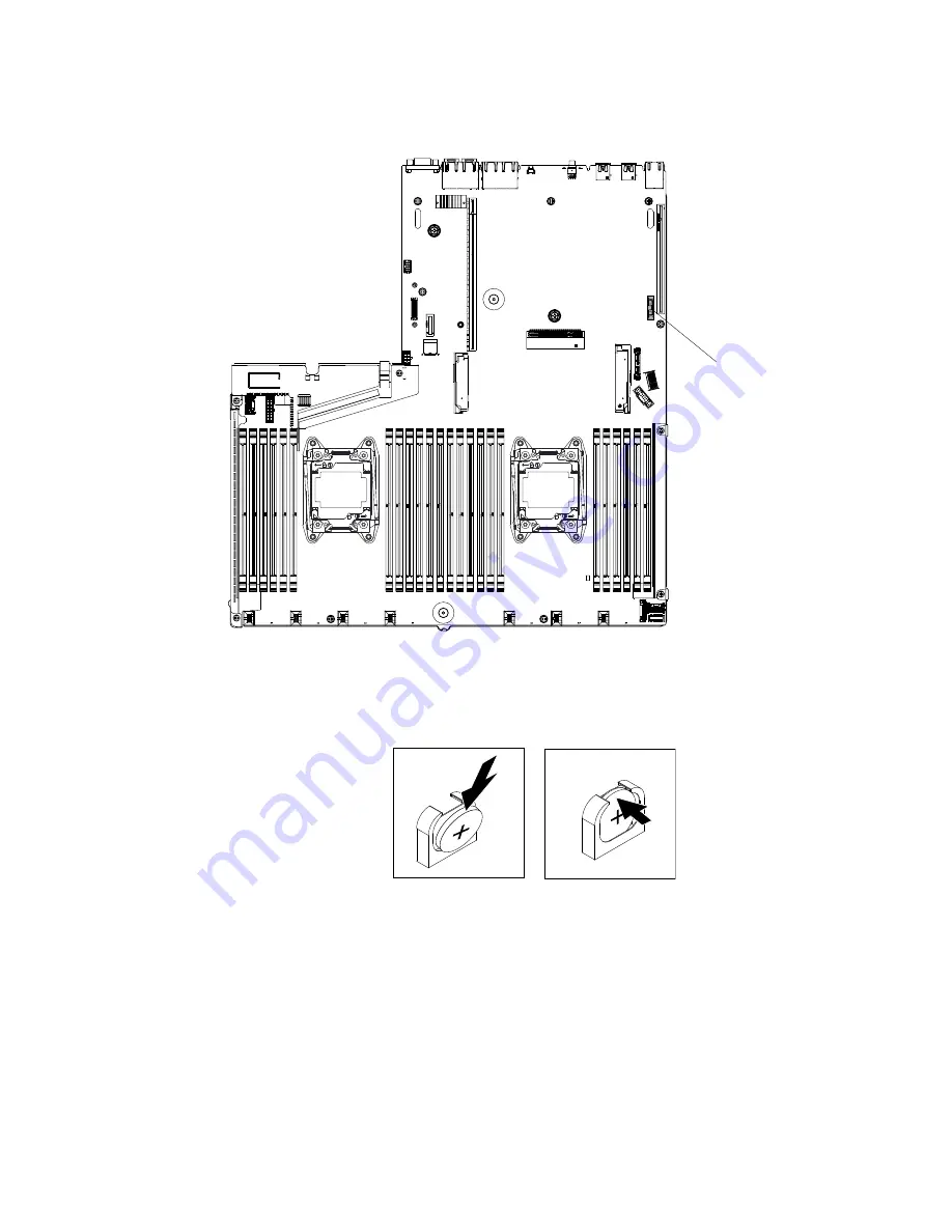
Locate the coin-cell battery connector on the system board.
Coin-cell battery
Figure 151. Location of the coin-cell battery connector on system board
a.
Tilt the battery so that you can insert it into the socket on the side opposite the battery clip.
Figure 152. Coin-cell battery installation
b.
Press the battery down into the socket until it clicks into place. Make sure that the battery clip
holds the battery securely.
c.
If you removed a rubber cover from the battery holder, use your fingers to install the battery
cover on top of the battery connector.
Step 7.
Reinstall PCI riser-card assembly 1 (see “Replacing a PCI riser-card assembly” on page 172 or
“Replacing the rear 2.5-inch hot-swap-drive kit” on page 143), if necessary.
Step 8.
Reinstall the cover (see “Replacing the cover” on page 120).
Step 9.
Slide the server into the rack.
Removing and replacing components
233
Содержание System x3550 M5
Страница 1: ...Lenovo System x3550 M5 Installation and Service Guide Machine Type 8869 ...
Страница 6: ...iv Lenovo System x3550 M5 Installation and Service Guide ...
Страница 66: ...52 Lenovo System x3550 M5 Installation and Service Guide ...
Страница 298: ...284 Lenovo System x3550 M5 Installation and Service Guide ...
Страница 1120: ...1106 Lenovo System x3550 M5 Installation and Service Guide ...
Страница 1124: ...1110 Lenovo System x3550 M5 Installation and Service Guide ...
Страница 1132: ...Taiwan BSMI RoHS declaration 1118 Lenovo System x3550 M5 Installation and Service Guide ...
Страница 1134: ...1120 Lenovo System x3550 M5 Installation and Service Guide ...
Страница 1142: ...1128 Lenovo System x3550 M5 Installation and Service Guide ...
Страница 1143: ......
Страница 1144: ......


