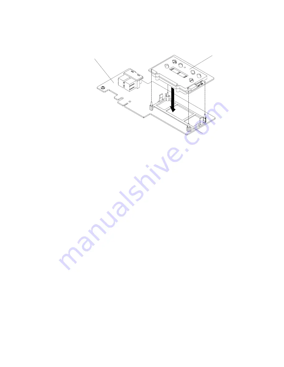
Step 5.
Align the memory module with the connector on the ServeRAID adapter and push it into the
connector until it is firmly seated.
ServeRAID adapter
ServeRAID
memory module
Retention
bracket
Figure 117. ServeRAID memory module installation
Step 6.
Reinstall the ServeRAID SAS/SATA controller (see “Replacing a ServeRAID SAS/SATA controller”
on page 185).
Step 7.
Reconnect the power cords and any cables that you removed.
Step 8.
Reinstall the cover (see “Replacing the cover” on page 120).
Step 9.
Slide the server into the rack.
Step 10. Turn on the peripheral devices and the server.
Removing a thermal kit (hot-swap fan)
Use this information to remove a thermal kit (hot-swap fan).
Attention:
It is not necessary to disconnect the power when removing the hot-swap fan. To ensure proper
server operation, replace a failed hot-swap fan within 30 seconds.
To remove a hot-swap-fan, complete the following steps:
Step 1.
Read the safety information that begins on “Safety” on page v and “Installation guidelines” on
page 116.
Step 2.
Remove the cover (see “Removing the cover” on page 119).
Removing and replacing components
193
Содержание System x3550 M5
Страница 1: ...Lenovo System x3550 M5 Installation and Service Guide Machine Type 8869 ...
Страница 6: ...iv Lenovo System x3550 M5 Installation and Service Guide ...
Страница 66: ...52 Lenovo System x3550 M5 Installation and Service Guide ...
Страница 298: ...284 Lenovo System x3550 M5 Installation and Service Guide ...
Страница 1120: ...1106 Lenovo System x3550 M5 Installation and Service Guide ...
Страница 1124: ...1110 Lenovo System x3550 M5 Installation and Service Guide ...
Страница 1132: ...Taiwan BSMI RoHS declaration 1118 Lenovo System x3550 M5 Installation and Service Guide ...
Страница 1134: ...1120 Lenovo System x3550 M5 Installation and Service Guide ...
Страница 1142: ...1128 Lenovo System x3550 M5 Installation and Service Guide ...
Страница 1143: ......
Страница 1144: ......


