KFU-
tronic
69
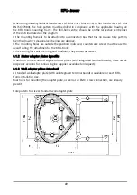
When using raised-cylindrical head screws (cf. DIN 912 / DIN 6912) or flat head screws (cf. DIN
EN ISO 7380), the hole pattern must be drilled in compliance with the applicable drawing on
the KFU-tronic mounting frame. The drill-hole centres should be on the respective centre lines
of the slots illustrated on the diagram.
If the mounting frame is to be attached to a connection box that has no square hole pattern,
then the drawing’s diagonal centre lines are decisive.
If the mounting holes are outside the positions indicated, countersunk screws must be used to
avoid fouling the attachment of the KFU-tronic.
If the existing flat seals are in a good condition, they should be reused
8.1.2
Motor adapter plates (specific)
In addition to the standard engine adapter plates (with integrated terminal boards), there are al-
so specific versions for various engine suppliers available (on request).
8.1.3
Wall adapter plates (standard)
A standard wall adapter plate (with an integrated terminal board) is available for each KFU-
tronic installation size.
Four holes for mounting the adapter plate, as well as an EMC screw connection, are already
present.
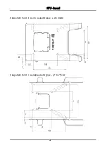
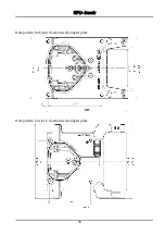
Hole pattern for size A standard wall adapter plate
Содержание KFUtronic Series
Страница 5: ...KFU tronic 4 ...
Страница 31: ...KFU tronic 30 5 3 Block diagram General structure of target value generation ...

