KFU-
tronic
27
DANGER!
The drive control may not be installed without an adapter plate!
Find a position that meets the required ambient conditions as described in the "Installation
requirements" section.
To achieve optimum self-convection of the drive control, ensure that the (EMC) screw
connection is facing upwards when installing.
Without any additional ventilation for the INVEOR (optional for BG C), it is only permitted
to be installed vertically.
Wiring
1.
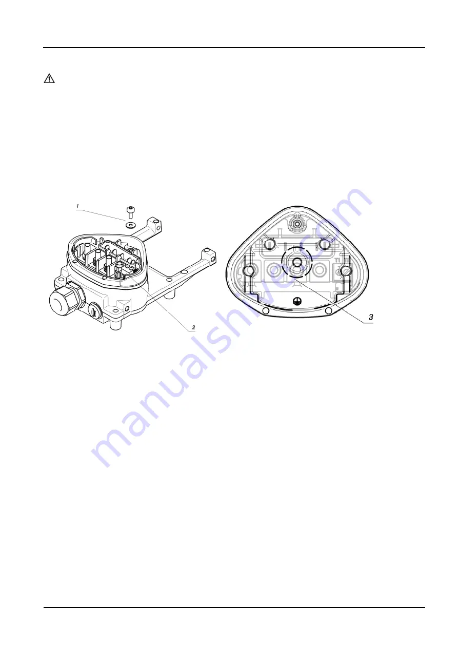
Release the screw (1) to remove the contact plate from the adapter plate.
The (M6) PE connection (3) is underneath this contact plate.
2.
Guide the connection cable from the motor to the adapter plate through the
integrated EMC screw connection.
3.
This connection has to be made to the same ground potential of the motor.
The cross-section of the equipotential bonding line must correspond to at least
the cross-section of the power cord.
4.
Reattach the contact plate using the screw (1).
5.
Wire the motor cable to contacts U, V, W (and star point in some cases) in the
connection terminal, as described in the "Basic connection versions" chapter.
Use cable shoes (M5) to do this.
6.
Before connecting an available motor PTC to the T1 and T2 terminals,
remove the preassembled short-circuit bridge (2).
The motor PTC is potential-free after connecting the KFU-tronic, therefore it must be
connected using a separate motor lead.
Replace the dummy screw with a suitable standard screw connection and
guide both ends to T1 and T2.
Содержание KFUtronic Series
Страница 5: ...KFU tronic 4 ...
Страница 31: ...KFU tronic 30 5 3 Block diagram General structure of target value generation ...


