Chapter 10 RA83/84/85/93/94/95 Series
Technical Reference
Operation Manual
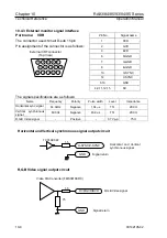
10.4.3 External monitor signal interface
Pin No.
Signal name
1 RVD
2 GVD
3 BVD
6 R-GND
7 G-GND
8 B-GND
13 H-SYNC
14 V-SYNC
5,10 GND
4,9,11,12,15 NC
Port name: VDR
The connector used: Small D-sub 15 pin
Pin assignment of the connector is as follows:
External CRT connector
(Top View)
1
2
3
4
5
6
7
8
9
10
11
12
13
14
15
The signal specifications are as follows:
Name Frequency
Polarity
Pulse
width
Level
Impedance
Horizontal sync signal
64.0kHz Negative 1.04
µ
s
TTL
200
Ω
Vertical synchronous
signal
60.0Hz Negative 46.9
us TTL
200
Ω
R,G,B Video signal
-
Positive
-
0.7 Vp-p
75
Ω
Horizontal and Vertical synchronous signal output circuit
1.5
GND
Signal return
H-SYNC/V-SYNC
TC74AC04F
Horizontal and Vertical
synchronous signal
R,G,B Video signal output circuit
Video D/A Converter (FMS3818KRC)
75
1.5
Signal return
R,G,B Video signal
GND
RVD/GVD/BVD
10-8
93142105-02

