


RA83/84/85/93/94/95 Series
Chapter 8
Operation Manual
Trouble Shooting And On Board Servicing
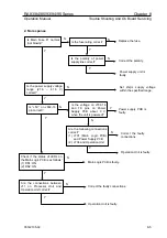
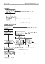
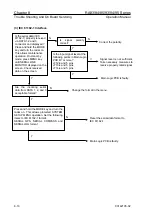
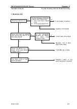
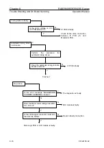
5. Faulty radar picture
Y
Y
Y
N
N
Y
HM PCB is faulty.
Modulator PCB is faulty.
N
Is background noise
present at Gain max
position?
N
Y
N
Y
Main Logic PCB is faulty.
N
Is the TX Drive signal on
TP2 on Modulator PCB
correct?
Is the receiver
sensitivity low in long
ranges?
Is the receiver sensitivity
normal throughout the entire
range scales?
Y
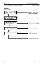
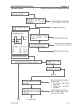
Is the error message
“AZIMUTH ABNORMAL”
shown?
Go to “9. Antenna
faults, Pulse selection
not operative”
Does the antenna
rotate freely?
Does the sweep line
skip near the HM
(Heading Marker)?
N
Is the error message
“HEADING LINE
ABNORMAL”
shown?
Y
N
Y
N
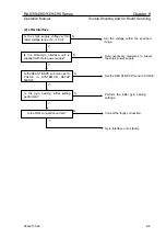
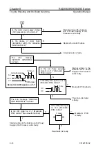
Is the radar echo displayed?
Y
Is the error message
“RADAR VIDEO
ABNORMAL” shown?
N
Go to “9. Antenna faults,
Radar echo abnormal.”
Main logic board is faulty.
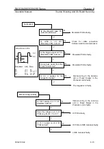
Go to “9. Antenna faults,
Radar echo abnormal.”
Go to “9. Antenna faults, Pulse
selection not operative.”
Main Logic PCB
is faulty
93142105-02
8-7