RA83/84/85/93/94/95 Series
Chapter 4
Operation Manual
Installation
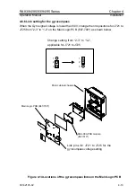
4.6.6 Link setting for the gyrocompass
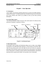
When the Gyro signal voltage is lower than 50V, change the link positions for J721 to
J725 from “2-3” to “1-2” on the Main Logic PCB (E47-700*) as shown below.
Change setting from “2-3” to “1-2”,
applicable for J721 to J725
1
2
3
1
2
3
KSA-08A PCB module
(E47-510*)
Link pins for J721 to J725 for the
gyrocompass voltage setting
Main cabinet chassis
Main Logic PCB (E47-700*)
Figure 4.14 Locations of the gyrocompass links on the Main Logic PCB
93142105-02
4-13


