Chapter 4 RA83/84/85/93/94/95 Series
Installation OperationManual
stacks, to avoid causing blind sectors on the radar screen as well as
contamination from engine exhaust on the radar antenna aperture.
(5) Provide sufficient servicing space.
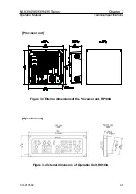
4.4.2 Processor and Operation Unit
(1) Select a location that provides good observation to radar screen and outside
environment.
(2) Locate the display so that it provides easy viewing from all likely operator’s
positions.
(3) Select a position safe and free of dampness, water spray, rain and direct sunlight.
(4) Provide enough space for servicing. Consider access to the rear panel for
connecting various cables.
(5) Position the processor unit as far as possible away from other radio equipment.
(6) Keep a safe distance from the magnetic compass: standard: 0.60 m, steering:
0.40 m.
4.5 Cable routing and connections
4.5.1 Antenna
(1) The cable connecting the antenna and display should be run separately away from
other cables such as, radio antenna feeders, power cables, etc. Under no
circumstances should it be in parallel arrangement with other cables. These
precautions are essential to avoid radio interference to/from other equipment
installed on the ship. If this is not possible, either cable set should be screened
with metal conduit or another form of shielding.
(2) Cable should be run as short as possible but be kept within the standard length to
achieve best radar performance.
(3) The copper braids of the cable must be grounded via a grounding stud in the
transceiver unit.
4.5.2 Processor Unit
(1) The Processor Unit must be grounded to the hull via a grounding stud at the rear
of the processor unit.
4-2
93142105-02

