Chapter 6 RA83/84/85/93/94/95 Series
Using The Menu
Operation Manual
6.8 Operating the AIS
NOTE: To use this function, the optional AIS interface module (PCB based) must be
installed inside the processor unit and connected to an external AIS transponder. The
installation of the module must be performed by an authorized KODEN service
personnel.
Reference description: APPENDIX 1 Installation of AIS module, AIS-100, Chapter 4
Installation.
6.8.1 Outline of the AIS
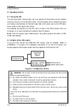
The AIS interface module receives the other ship’s information sent from an external
AIS transponder and displays the AIS symbols and data. (NOTE: The AIS transponder
transmits own ship’s information at certain interval and also receives the navigational
information broadcast from ships located within the AIS reception coverage.
6.8.2 Setting the AIS to work
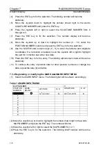
(1) In the DISP menu select AIS and select ON.
Indication Meaning
Selection
AIS
AIS data display
OFF, SYMBOL OFF, ON
(2) In the RADAR menu select LIM (AIS range). Selecting the LIM range causes the
AIS symbols to be displayed within the LIM range.
(3) The AIS symbols are displayed on the target echoes, which are termed “activated
target.” The AIS interface can handle up to 20 targets for AIS processing. The
targets of 21 up to 40 are deemed to be “sleeping targets” or unprocessed targets,
causing the alarm message “Number of targets have exceeded the limit” to be
shown on the screen.
(4) To prevent potential dangerous targets from being unprocessed, always keep the
LIM range to allow a total number of activated targets to be within 20. To view the
AIS data of a specific activated target, set a target ID number in the RADAR menu
to an associated TARGET ID shown on the screen.
6.8.3 AIS data display
MMSI
An acronym of “Maritime Mobile Service Identity”, which
means the identification number of each ship that carries the
AIS transponder. The number is assigned by the IMO.
CPA
Closest Point of Approach
TCPA
Time to CPA
CSE/COG
Course/Course Over Ground
6-32
93142105-02

