Chapter 8
RA83/84/85/93/94/95 Series
Trouble Shooting And On Board Servicing Operation
Manual
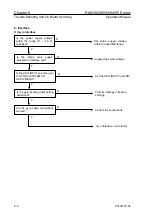
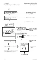
(3) IEC 61162-1 Interface
N
N
Y
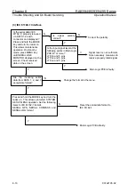
Correct the polarity.
N
Y
Y
Main Logic PCB is faulty.
N
Signal level is not sufficient.
Take necessary measures to
receive properly rated signal.
Y
Change the format in the menu.
N
Main Logic PCB is faulty.
Press and hold the MODE key and turn the
radar on. This allows protected SYSTEM
SETUP MENU operation. Set the following
items to IEC 61162-1 format.
SERIAL GPS, SERIAL COMPASS and
SERIAL LOG format
Y
Are the incoming serial
data from DATA 1, 2, and 3
acceptable format?
Is the input signal level at the
following points in Main Logic
PCB 4V or more?
J712-4 and 5 pins
J713-4 and 5 pins
J714-4 and 5 pins
Is the serial data (IEC
61162-1) properly received
via DATA 1,2 and 3
connector and displayed?
Press and hold the MODE
key and turn the radar on.
This allows maintenance
operation. On stand-by
mode, press MENU key
until SERIAL LINE
MONITOR displayed on the
screen. Check received
data on the screen.
Is signal polarity
correct?
Reset the serial data format to
IEC 61162-1.
8-10
93142105-02


