


Chapter 4 RA83/84/85/93/94/95 Series
Installation OperationManual
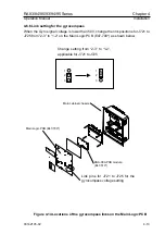
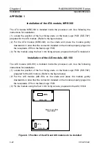
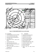
Main Logic PCB. (Refer to the figure A.2)
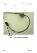
(7) Reconnect all cables to the Main Logic PCB.
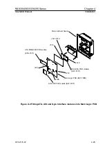
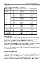
Cable connecting list
No.
KSA-08A (E47-510A)
Main Logic PCB (E47-700*)
1 J512
J708
2 J515
J707
3 J517/518
J718
GYRO connector pinouts and cable color coding designation:
Cable type name
Port name
Pin No.
Signal name
Color code
CW-388-5M GYRO 1
S1
Red
dot/Orange
2
S2
Black
dot/Orange
3
S3
Red
dot/Grey
4
R1
Red
dot/White
5
R2
Black
dot/White
6
COM
Red
dot/Yellow
7
GND
Shield
8
LOG1
Red
dot/Pink
9
LOG2
Black
dot/Pink
10
NC
4-24
93142105-02