RA83/84/85/93/94/95 Series
Chapter 8
Operation Manual
Trouble Shooting And On Board Servicing
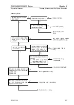
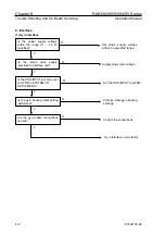
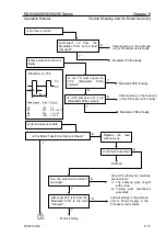
No transmit
N
Y
N
Y
N
Y
N
Y
N
Is the trigger signal on TP2
(Modulator PCB) normal?
Is any buzz heard from the
Pulse Transformer?
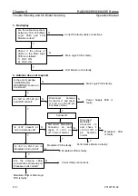
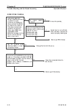
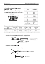
Pulse length A(ns) B(ms)
SP 100
0.5
M1
200
0.67 or 0.77
M2
550
1 or 1.25
LP
1050
2 or 2.5
0 V
5 V
Waveform on TP2
B
A
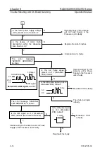
Is 6.3 V applied to the
magnetron heater?
Is +250 V on J2-1
(Modulator PCB) normal?
Is the Mod-HT fuse F3
normal (not blown)?
Y
Modulator PCB is faulty.
Check for cable connection
between antenna and processor.
Modulator PCB is faulty.
Modulator PCB is faulty.
Internal wiring in the Antenna
unit or Power Supply in the
Processor unit is faulty.
The magnetron is faulty.
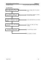
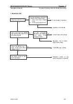
N
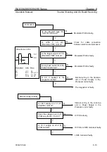
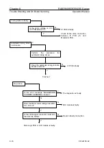
Is +24V supply on J1-1 (IF
Amplifier) normal?
Manual tuning is faulty
N
Y
Y
Does the voltage on J2-3 (IF
PCB) vary from 6 V to 9 V?
N
Is +5 V supply on J2-2 (IF
PCB) normal?
Y
Internal wiring in the Antenna
unit or Power Supply in the
Processor unit is faulty.
IF PCB is faulty.
IF PCB or LNFE module is faulty.
LNFE module is faulty.
93142105-02
8-15


