58
Chapter 4
Troubleshooting
Function Specific Troubleshooting
Step 3.
Press the
SYSTEM CONFIG
softkey.
Step 4.
Select the DHCP ENABLED field using the cursor keys and then press the
OFF
softkey.
Step 5.
Select the AUTO-IP ENABLED field using the cursor keys and then press the
OFF
softkey.
Step 6.
Enter the following IP address and subnet mask using the enter keys. For selecting the
MANUAL IP ADDR or MANUAL SUBNET MASK field, use the cursor keys.
IP Address: 192.168.0.1
Subnet Mask: 255.255.255.0
Step 7.
Set up the IP address/subnet mask for the external PC.
a.
Double-click “
My Computer
” icon on Windows desktop of the external PC. And
double-click
Control Panel
. The Control Panel window will appear.
b.
In the Control Panel window, double-click
Network
. The Network dialog box will
appear. In the
Configuration
tab, select
TCP/IP
(display it in revers video) and press
the
Properties
button.
c.
The dialog box appears. If
Specify an IP address
has been selected, record the IP
address and subnet mask.
d.
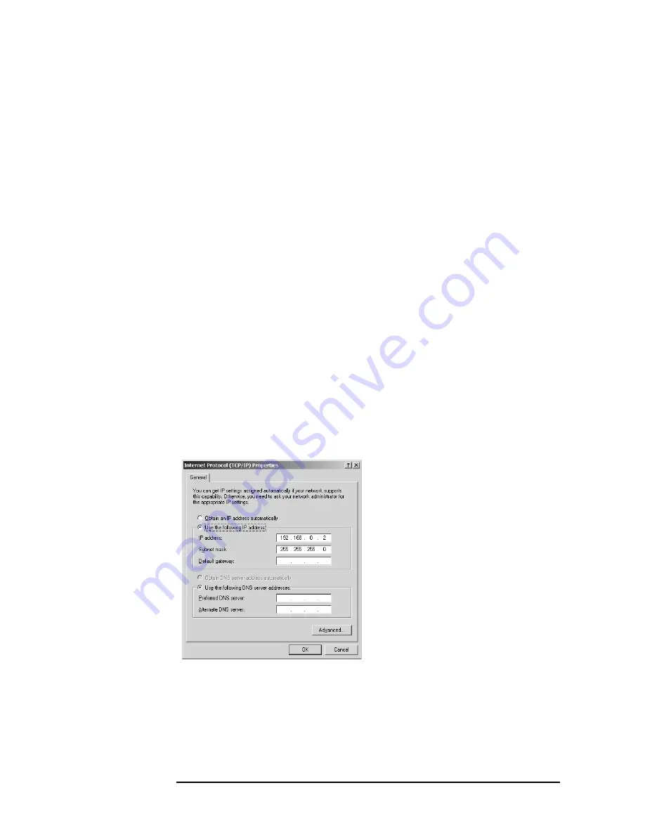
If the
Obtain an IP address automatically
has been selected, select the
Specify an IP
address
. Enter the IP address xxx.xxx.xxx.y and subnet mask xxx.xxx.xxx.xxx as
shown in
. The letters x represent the IP address and subnet mask of the
E4981A. The letter y is different from the IP address of the E4981A. Press the
OK
button. Then, restart the external PC.
Figure 4-6
Network Dialog Box (“IP Address” Tab)
Step 8.
By clicking “OK” button, the network settings take effect. Verify the E4981A LAN
settings and response to a command from the external computer as follows:
a.
On the external computer, click "Start" button in the Windows Start menu bar using a
mouse.
㪼㪋㪐㪏㪇㪸㫊㪼㪈㪇㪌㪌
Содержание E4981A
Страница 1: ...Keysight E4981A 120 Hz 1 kHz 1 MHz Capacitance Meter Service Guide ...
Страница 2: ......
Страница 13: ...Contents 11 L 145 M 145 N 145 O 146 P 146 Q 146 R 147 S 147 T 147 U 148 Warning Message 149 ...
Страница 14: ...12 Contents ...
Страница 70: ...68 Chapter4 Troubleshooting Performance test failure troubleshooting ...
Страница 84: ...82 Chapter5 Replaceable Parts Replaceable Parts List Front Panel Figure 5 12 Front Panel ...
Страница 96: ...94 Chapter6 Replacement Procedure 3 4 Rack Module Top Replacement Figure 6 3 Screw Fastening Sequence ...
Страница 98: ...96 Chapter6 Replacement Procedure PSU Deck Assembly Removale Figure 6 4 PSU Deck Assembly Removal ...
Страница 100: ...98 Chapter6 Replacement Procedure PSU Assembly Replacement Figure 6 5 PSU Assembly Replacement ...
Страница 102: ...100 Chapter6 Replacement Procedure Front Chassis Assembly Removal Figure 6 6 Front Chassis Assembly Removal ...
Страница 104: ...102 Chapter6 Replacement Procedure Front Panel Assembly Removal Figure 6 7 Front Panel Assembly Removal ...
Страница 108: ...106 Chapter6 Replacement Procedure Interface Board Assembly Replacement Figure 6 10 Screw Fastening Sequence ...
Страница 118: ...116 Chapter6 Replacement Procedure Power Inlet Assembly Replacement Figure 6 17 Power Inlet Assembly Replacement ...
Страница 122: ...120 Chapter6 Replacement Procedure Inverter Assembly Replacement Figure 6 20 Inverter Assembly Replacement ...
Страница 124: ...122 Chapter6 Replacement Procedure Display Support Removal Figure 6 21 Display Support Removal ...
Страница 132: ...130 Chapter7 Post Repair Procedures Post Repair Procedures ...
Страница 138: ...136 AppendixB Firmware Update Update the E4981A firmware using USB cable ...
Страница 139: ...137 1 Chapter Title 2 Chapter Title 4 Chapter Title 5 Chapter Title C Power Requirement C Power Requirement ...
Страница 142: ...140 AppendixC Power Requirement Power Requirements ...


