W
W
W
W
W i n P a s s R e f e r e n c e M a n u a l
i n P a s s R e f e r e n c e M a n u a l
i n P a s s R e f e r e n c e M a n u a l
i n P a s s R e f e r e n c e M a n u a l
i n P a s s R e f e r e n c e M a n u a l
DN1237-0003 © 1997-2000 Kantech Systems Inc.
3 4
3 4
3 4
3 4
3 4
KT-LCD4501 - LCD Time & Date Display Module
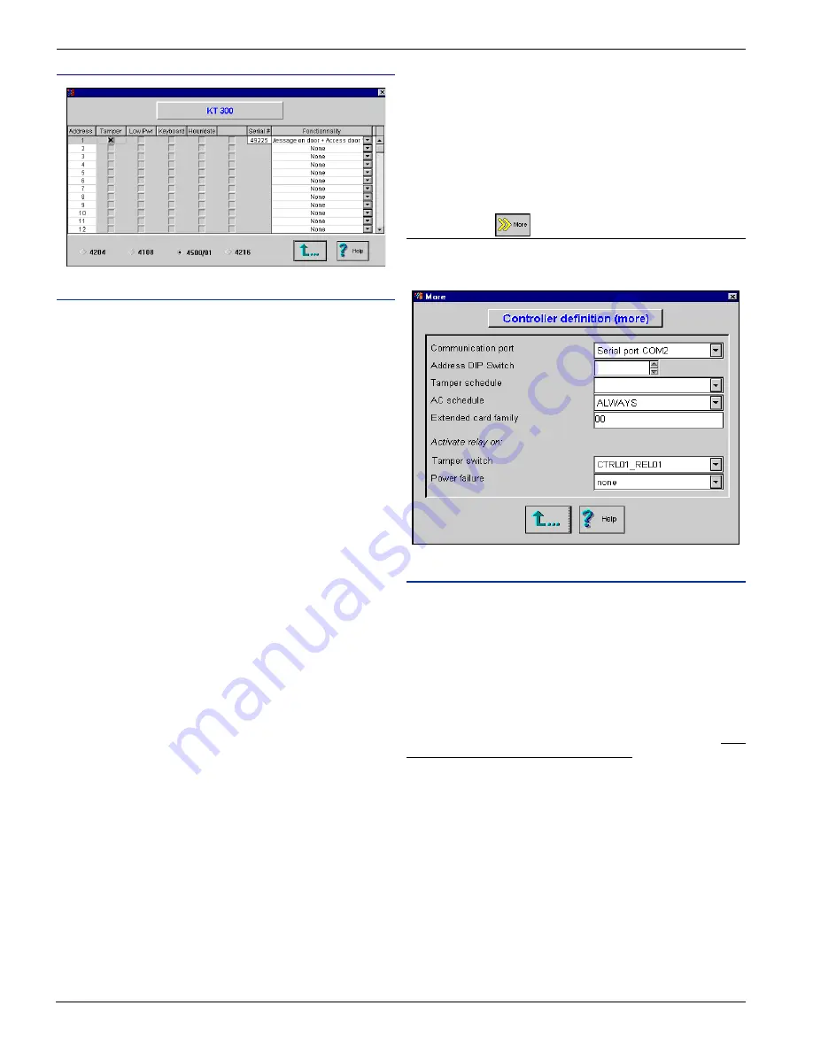
Field Definition
Note : Before you make any selection, you have to select the
module’s functionality.
Address
This field identifies the physical address of the module.
Tamper
If selected, the system will generated a Combus module defect
event on the controller, whenever the tamper is disconnected from
the module (some keypads are not equippled with a tamper).
Low Pwr
If selected, the system will generate a a Combus module defect
event on the controller, for a lost of power from the module.
Keyboard
Must be selected to be used as a keypad for access or time and
attendance. If you wish to use the LCD module as a keypad
(access), then you have to select the “Integrated in reader” field
in the “Keypad type”of the controller definition menu.
Hour/Date
Must be selected if you wish to display the time and date on the
keypad screen.
Serial #
Register the serial number of the module, showed in the List of
unassigned components screen.
Functionality
Select the module’s functionality:
1) Message on door:
When you select this option, this means that the module will
not be used as a keypad (door access). It can therefore be used
only to display the time and date (you have to select “Hour/
date” field).
2) Message on door + Access door 1:
Selecting this option means that the module will be used as a
keypad for access on door 1. To use as a keypad, you have to
select the “Integrated in reader” field in the “Keypad type”of
the controller definition menu. You can also display the time
and date by selecting the “Hour/time” field.
3) Message on door + Access door 2:
Selecting this option means that the module will be used as a
keypad for access on door 2. To use as a keypad, you have to
select the “Integrated in reader” field in the “Keypad type”of
the controller definition menu. You can also display the time
and date by selecting the “Hour/time” field.
Note: No matter which feature is chosen, the module will always
display the version of the firmware every time the power is
switched on. If you wish to use the LCD module as a keypad
(access), then you have to select the “Integrated in reader” field
in the “Keypad type”of the controller definition menu.
“More” button
If you press the more button from the controller definition screen,
the system will display the following screen:
Field Definition
Communication port
Select the serial port on which the controller bus will be connected
to the host computer. To select the baud communication speed,
refer to Section 5 under workstation definition menu under “Port
setting” button.
Address DIP switch
This field applies only if you are using KT-200 controllers. The
address selected here must be the same as the physical address
on the controller. Enter the controller’s address (1 to 32 max). Two
controllers cannot share the same address.
Tamper schedule
Select a schedule to activate tamper switch monitoring.
AC schedule
Select a schedule to activate AC monitoring.
Extended card family
Enter the extended card family when applicable. When selected,
you will have to enter these numbers on the card definition screen.
Activate relay on
Allows you to select a relay which will be activated on the events:
“Tamper switch” (KT-200 only) and “Power failure”.


