W
W
W
W
W i n P a s s R e f e r e n c e M a n u a l
i n P a s s R e f e r e n c e M a n u a l
i n P a s s R e f e r e n c e M a n u a l
i n P a s s R e f e r e n c e M a n u a l
i n P a s s R e f e r e n c e M a n u a l
DN1237-0003 © 1997-2000 Kantech Systems Inc.
4 8
4 8
4 8
4 8
4 8
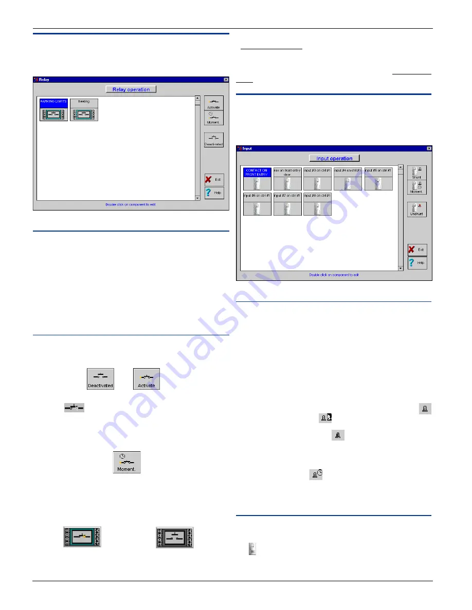
Relay Operation
This feature allows manual operations on relays such as: activa-
tion or deactivation. It also shows the actual state of the relays.
Field Definition
Relay name
Label identifying the relay in the system. The relay name is
displayed on top of each relay graphic.
How to select a relay
To select a relay just click on the drawing for that relay. The
selected relay’s name will appear in capital white letters high-
lighted with a blue background. All manual operations are ex-
ecuted on the selected relay.
Buttons
Activate / deactivate relay
To activate or deactivate a relay, click on the appropriate button.
When a relay is activated the relay closes and the animation will
be visible
.
Momentarily activation
The duration of a temporary activation is programmed in Relay
Definition.
Relay state
The relay state is represented by a drawing of the relay. This
drawing can display two states: activated and deactivated.
Activated
Deactivated
Unknown state
The relay state is unknown when the system has not communi-
cated with the controller. The unknown state is represented by
a blue question mark.
Communication state
Communication failures or error are represented by a red question
mark.
Input Operation
This screen allows the operator to graphically view the actual
input status. It also allows manual supervision or shunting
inputs.
Field Definition
Input name
Description of input. The description is displayed on top of the
input graphic.
To select an input
To select an input, just click on the specific input drawing. The
selected input’s name will appear in capital white letters high-
lighted with a blue background. All manual operations are ex-
ecuted on the selected input.
Shunt / Unshunt Input
An input can be shunted by a schedule, another input, a door
or manually by an operator
. An input which is shunted by an
operator overrides the monitoring schedule. Therefore, only the
operator can unshunt the input
. An input is unshunted only
if its schedule is valid. The manual unshunt will modify only the
input which has been manually shunted.
Momentary shunt
The momentary shunt
has the same criteria as the shunt
button. The duration will depend on what has been specified in
“Input Definition” and will begin once the button is activated.
States
Active/Inactive State
An input is active when the detector’s light changes from grey to
red (active = red, inactive = grey).


