5 Installation
16
5 Installation
5.1 Installation
conditions
5.1.1 General
Compliance with the following points is required for installation:
• Ensure that the flow direction corresponds to the marking,
if there is one.
• Ensure that the maximum torque specification is
maintained for all flange screws.
Torque information
on
page 90.
• Secure flange screws and nuts against pipe vibrations.
• Install devices without mechanical tension (torsion, bend).
• Install flange and wafer-type devices with coplanar
counter flanges and use only appropriate gaskets.
• Use only gaskets made from a material that is compatible
with the medium being measured and its temperature.
• Ensure that gaskets do no extend into the flow area since
possible turbulence could influence the device accuracy.
• Ensure that no impermissible forces or moments act on
the device owing to the piping.
• Ensure that the temperature limits for the device are being
adhered to during operation.
• Avoid vacuum shocks in the piping. Vacuum shocks can
destroy the liner and the device.
• Do not remove the plugs for the cable glands until you are
ready to install the electrical cables.
• Make sure that the gaskets for the housing cover are
seated properly. Carefully close the cover. Tighten the
cover screws.
• Install the remote-mount transmitter at a location that is
free of vibrations to a large extent.
• Do not expose the transmitter or the sensor to direct
sunlight; provide protection from the sun as needed.
• Ensure that sufficient cooling is provided whenever
installing the transmitter in a control cabinet.
• Ensure that the remote-mount transmitter and the
associated sensor are correctly assigned (paired).
Devices that form a pair have the same numeric suffix;
e.g., the X001 sensor is paired with the Y001 transmitter
or the X002 sensor is paired with the Y002 transmitter;
this is indicated on the rating plate.
5.1.2 Brackets
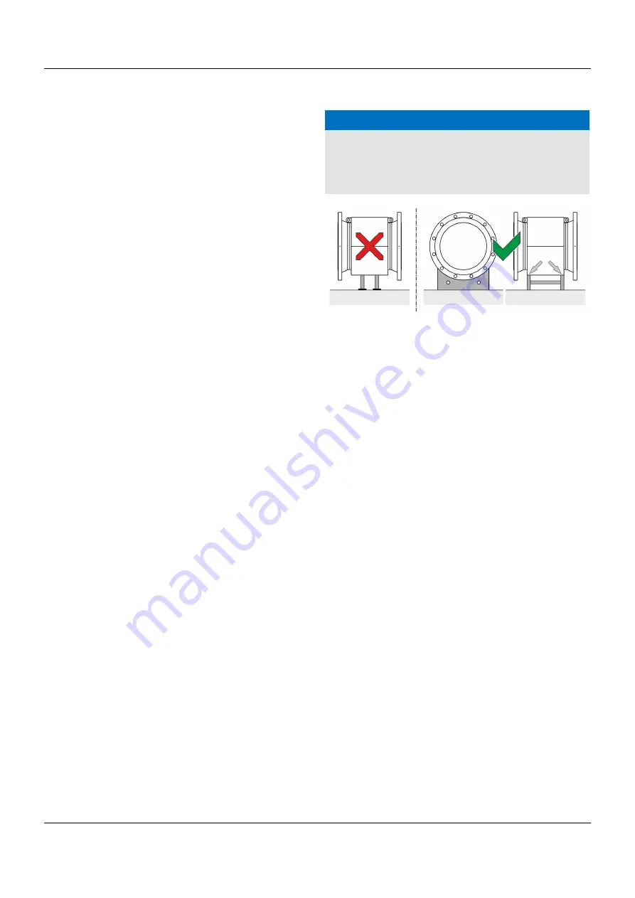
NOTICE
Potential damage to the device!
Improper support for the device may result in a deformed
housing and damage to internal magnetic coils.
• Place the supports at the edge of the sensor housing (see
arrows in
Figure 9
).
Figure 9: Support for nominal diameters larger than DN 400
Devices with nominal diameters larger than DN 400 must be
mounted on a sufficiently strong foundation with support.
5.1.3
Gaskets
The following points must be observed when installing gaskets:
• To achieve the best results, make sure that the gaskets
and meter tube fit concentrically.
• To make sure that the flow profile is not distorted, the
gaskets may not intrude in the piping cross-section.
• The use of graphite with the flange or process connection
gaskets is prohibited. This is because, in some instances,
an electrically conductive coating may form on the inside
of the meter tube.
Device with hard rubber or soft rubber lining
• Additional gaskets are always required for devices with lining
made of hard rubber or soft rubber.
• The use of rubber gaskets or sealing materials that are similar
to rubber is recommended by the manufacturer.
• When selecting the seals ensure that the torques detailed in
Torque information
on page 90 are not exceeded.
Devices with lining made of PTFE, PFA or ETFE
• No additional gaskets are required for devices with lining
made of PTFE, PFA or ETFE.
Содержание 406060
Страница 2: ......
Страница 98: ...13 Appendix 98 13 3 Declarations of conformity 13 3 1 JUMO flowTRANS MAG S10...
Страница 99: ...13 Appendix 99...
Страница 100: ...13 Appendix 100...
Страница 101: ...13 Appendix 101...
Страница 102: ...13 Appendix 102...
Страница 103: ...13 Appendix 103...
Страница 104: ...13 Appendix 104 13 3 2 JUMO flowTRANS MAG H10...
Страница 105: ...13 Appendix 105...
Страница 106: ...13 Appendix 106...
Страница 107: ...13 Appendix 107...
Страница 108: ...13 Appendix 108...
Страница 109: ...13 Appendix 109...
Страница 110: ...13 Appendix 110 13 3 3 JUMO flowTRANS MAG 10...
Страница 111: ...13 Appendix 111...
Страница 112: ...13 Appendix 112...
Страница 113: ...13 Appendix 113...
Страница 115: ......


