


Optidrive P2 Advanced User Guide Rev 2.00
6
www.invertekdrives.com
Opt
idr
ive
P2
Par
ame
ter
Se
t
Ov
er
view
1
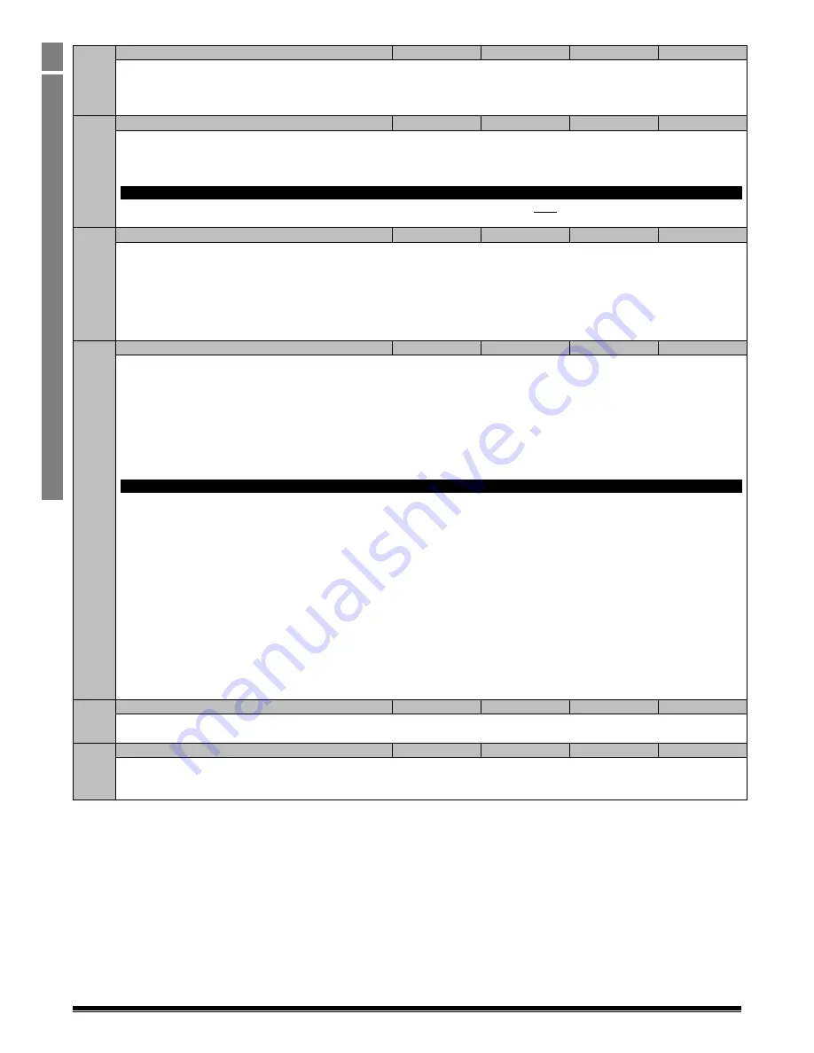
P1-09
Motor Rated Frequency
10
500
60 (60)
Hz
This parameter should be set to the rated (nameplate) frequency of the motor.
The factory default setting of this parameter is drive model dependent as follows :-
All kW models (e.g. ODP-2-xxxxx-xKFxx) : Factory setting = 50Hz
All HP models (e.g. ODP-2-xxxxx-xHFxx) : Factory setting = 60 Hz
P1-10
Motor Rated Speed
0
30000
0
Rpm
This parameter can optionally be set to the rated (nameplate) rpm of the motor. When set to the default value of zero, all speed
related parameters are displayed in Hz, and the slip compensation for the motor is disabled. Entering the value from the motor
nameplate enables the slip compensation function, and the Optidrive display will now show motor speed in estimated rpm. All speed
related parameters, such as Minimum and Maximum Speed, Preset Speeds etc. will also be displayed in Rpm.
Note
When the drive is operated with the optional Encoder Feedback Interface, this parameter must be set to the correct nameplate Rpm of
the connected motor.
P1-11
V/F Mode Voltage Boost
0.0
See Below
See Below
%
This parameter is effective only when operating in V/F Mode (P4-01 = 2).
Voltage boost is used to increase the applied motor voltage at low output frequencies, in order to improve low speed and starting
torque. Excessive voltage boost levels may result in increased motor current and temperature, and force ventilation of the motor may
be required.
An automatic setting (
) is also possible, whereby the Optidrive will automatically adjust this parameter based on the motor
parameters measured during an autotune.
The factory default and maximum limit for this parameter are drive model dependent, refer to section 0 for further information
P1-12
Primary Command Source Mode
0
6
0
-
0 : Terminal Control
. The drive responds directly to signals applied to the control terminals.
1 : Uni-directional Keypad Control
1)2)3)
The drive can be controlled in the forward direction only using an external or remote Keypad
2 : Bi-directional Keypad Control
4)
The drive can be controlled in the forward and reverse directions using an external or remote
Keypad. Pressing the keypad START button toggles between forward and reverse.
3 : PID Control
. The output frequency is controlled by the internal PID controller.
4 : Fieldbus Control
. Control via Modbus RTU if no fieldbus interface option is present, otherwise control is from the fieldbus option
module interface
5 : Slave Mode
. The drive acts as a Slave to a connected Optidrive operating in Master Mode
6 : CAN bus Control.
Control via CAN bus connected to the RJ45 serial interface connector
Note
1)
When operating with P1-12 = 1 or 2, the drive will not operate the motor unless the enable signal is present (e.g. Control
Terminals 1 & 2 are linked together), regardless of the setting of P2-37. If P2-37 > = 4, the drive will start when the link is
closed between terminals 1 & 2, and will not require the keypad start button to be pressed. If P2-37 < 4, the Start Button
must be pressed to operate the drive after the link is closed between terminals 1 & 2.
2)
The motor direction of rotation may still be controlled by signals applied to the digital inputs, dependent on the setting of
P1-13, e.g. the motor can still be controlled in both forward and reverse directions if required, however the Reverse direction
function of the Start key is disabled.
3)
When operating in this mode and utilising a setting of P1-13 that allows preset speeds to be also selected from the drive
digital inputs, setting a negative value in the preset speed parameter will cause the drive to reverse the direction of motor
rotation.
4)
When P1-12 = 2, the direction of motor rotation may be changed by any of the following :-
a.
Pressing the keypad Start button
b.
A Reverse Digital Input, dependent on the setting of P1-13
c.
Selecting a Negative Preset Speed
It is important to ensure that a combination of the above used incorrectly does not result in unexpected operation.
P1-13
Digital Inputs Function Select
0
21
1
-
Defines the function of the digital inputs depending on the control mode setting in
P1-12. See section 1.7 on page 30 for further information.
P1-14
Extended Menu Access Code
0
30000
0
-
Parameter Access Control. The following settings are applicable :
P1-14 = P2-40 (Factory Setting = 101) : Allows access to Parameter Groups 0 – 5
P1-14 = P6-30 (Factory Setting = 201) : Allows Access to all drive parameters


