Intel
®
Modular Server System Service Guide
59
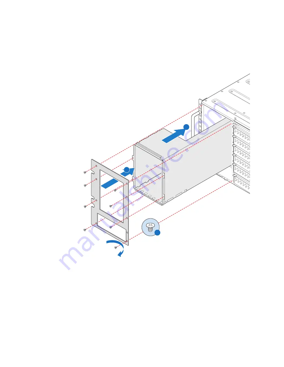
3. Install the HDD Bay Module bezel (see letter “B” in
Figure 44
) and secure with eight
screws taking care not to fully tighten the screws until all eight are in place (see letter
“C” in
Figure 44
).
Do not over tighten the screws holding the bezel.
Figure 44. Installing the 3.5-inch Hard Disk Drive Bay Module
AF0031
B
C
A
Содержание MFSYS25V2
Страница 4: ...iv Intel Modular Server System Service Guide ...
Страница 14: ...xiv Intel Modular Server System Service Guide ...
Страница 16: ...xvi Intel Modular Server System Service Guide ...
Страница 82: ...66 Intel Modular Server System Service Guide ...
Страница 137: ...Intel Modular Server System Service Guide 121 Figure 71 Storage Layout Graphical View ...
Страница 143: ...Intel Modular Server System Service Guide 127 Figure 77 Diagnostic Tests Figure 78 System Information Report Download ...
Страница 144: ...128 Intel Modular Server System Service Guide Figure 79 System Information Report ...
Страница 157: ...Intel Modular Server System Service Guide 141 Figure 91 Settings Event Policies Configuration Screen ...
Страница 172: ...156 Intel Modular Server System Service Guide ...
Страница 186: ...170 Intel Modular Server System Service Guide ...
Страница 198: ...182 Intel Modular Server System Service Guide ...


