Intel
®
Modular Server System Service Guide
13
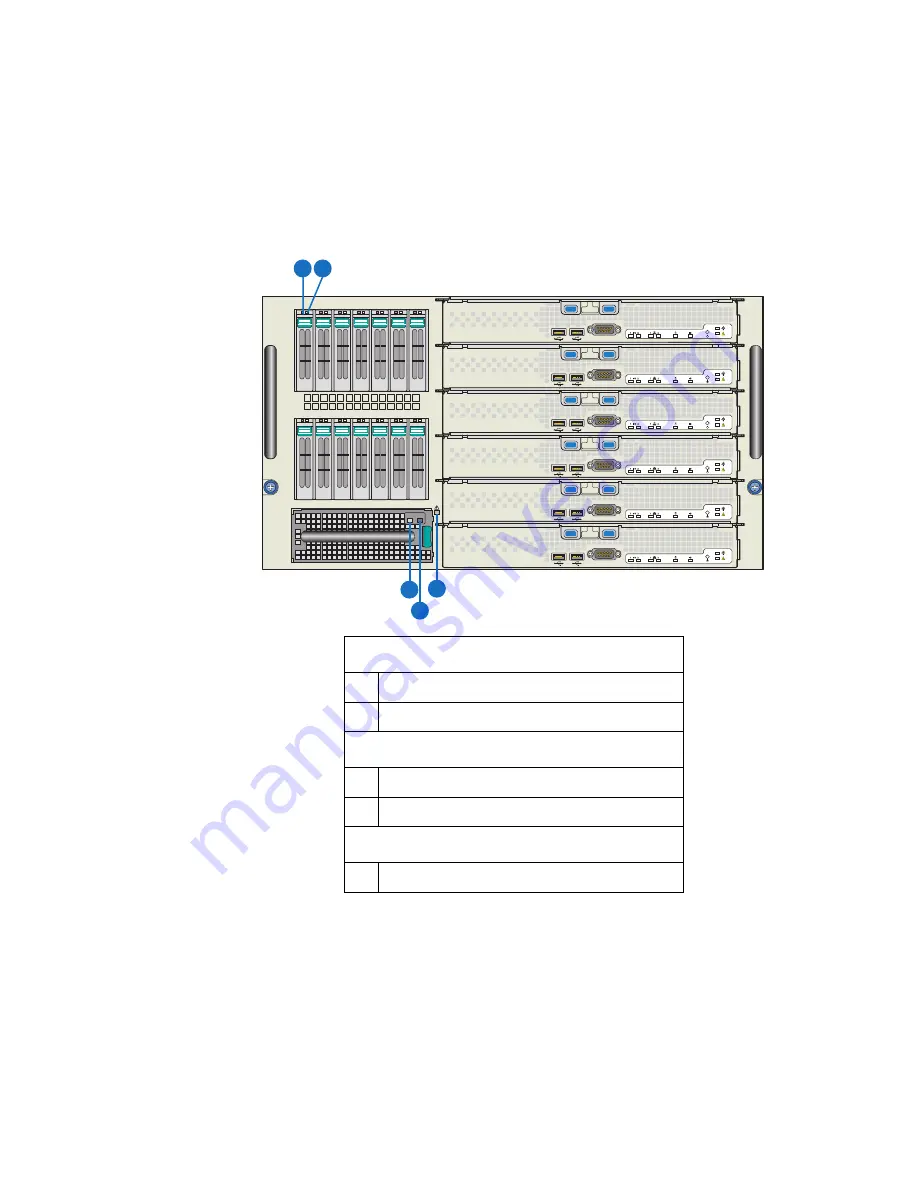
Front Chassis Connectors and Indicators
The indicator modes for the Hard Drive Carrier, I/O Cooling Module, and Chassis
indicators illustrated in the following figures are described in
“Diagnostic LED
Information” on page 153
.
Figure 6. Intel
®
Modular Server System MFSYS25 Front Chassis
Connectors and Indicators
Hard Drive Carrier
A
Hard drive power/activity LED – Green
B
Hard drive fault LED – Amber
I/O Cooling Module
C
I/O cooling module power LED – Green
D
I/O cooling module fault LED – Amber
Chassis
E
System Fault LED - Amber
1
2
3
4
5
6
7
8
9
10
11
12
13
14
1
2
3
4
5
6
A
AF00206
3
B
C
D
E
Содержание MFSYS25V2
Страница 4: ...iv Intel Modular Server System Service Guide ...
Страница 14: ...xiv Intel Modular Server System Service Guide ...
Страница 16: ...xvi Intel Modular Server System Service Guide ...
Страница 82: ...66 Intel Modular Server System Service Guide ...
Страница 137: ...Intel Modular Server System Service Guide 121 Figure 71 Storage Layout Graphical View ...
Страница 143: ...Intel Modular Server System Service Guide 127 Figure 77 Diagnostic Tests Figure 78 System Information Report Download ...
Страница 144: ...128 Intel Modular Server System Service Guide Figure 79 System Information Report ...
Страница 157: ...Intel Modular Server System Service Guide 141 Figure 91 Settings Event Policies Configuration Screen ...
Страница 172: ...156 Intel Modular Server System Service Guide ...
Страница 186: ...170 Intel Modular Server System Service Guide ...
Страница 198: ...182 Intel Modular Server System Service Guide ...


