background image

Hardware Options Installation 

Preparing the Server 

Before installing or removing any options, prepare the server by performing the 
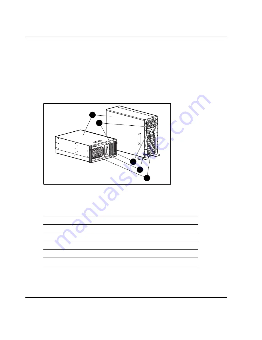
following procedures. Refer to Figure 3-1 and Table 3-1 to review chassis 
components. 

Chassis Components 


1

2

3

5

4

Figure 3-1:  Identifying rack and tower chassis 
components 


Table 3-1:  Rack and Tower Chassis Components 

Item Description 

1 Access 

panel 

Removable media bays 

3 CD-ROM 

drive 

4 Diskette 

drive 

5 Hard 

drive 

bays 

3-2


HP ProLiant ML350 Generation 3 Server Setup and Installation Guide 


HP CONFIDENTIAL


Writer: Richard O. Heath File Name: d-ch3 Hardware Options Installation.doc 

Codename: Steel Venom Part Number: 316354-001 Last Saved On: 12/6/02 3:06 PM 

Содержание ML350T06 - E5520 Sff Us Svr

Страница 1: ...HP ProLiant ML350 Generation 3 Server Setup and Installation Guide March 2003 First Edition Part Number 316354 001 ...

Страница 2: ...wlett Packard Company shall not be liable for technical or editorial errors or omissions contained herein The information in this document is provided as is without warranty of any kind and is subject to change without notice The warranties for HP products are set forth in the express limited warranty statements accompanying such products Nothing herein should be construed as constituting an addit...

Страница 3: ...er Features Standard Hardware Features 1 4 Tower Server Front Panel Components and Drive Bay Dimensions 1 4 Rack Server Front Panel Components and Drive Bay Dimensions 1 6 Tower Server Rear Panel Components 1 7 Rack Server Rear Panel Components 1 9 System Board Components 1 10 LEDs and Buttons 1 12 Processors 1 13 System Memory 1 13 Expansion Slots 1 13 Storage Controller 1 13 Network Interface Co...

Страница 4: ...s 2 12 System Configuration Switch Setting 2 13 Installing Component Rails on the Server 2 14 Installing the Cable Management Arm Bracket 2 16 Securing the Mounting Hardware to the Rack 2 17 Marking with the Template 2 17 Inserting Cage Nuts into the Rack Frame 2 18 Installing the Mounting Bracket Slide Assembly 2 19 Installing the Server into Round Hole Racks 2 20 Converting the Mounting Bracket ...

Страница 5: ... Drive 3 13 Installing a Device into a Removable Media Bay 3 15 Removing a Device from Removable Media Bay 3 20 Installing an Expansion Board 3 22 Removing the Fan Baffle 3 27 Memory Modules 3 28 Technical Information and Important Guidelines 3 28 Interleaving and Non Interleaving Memory Configuration 3 29 Installing a Memory Module 3 30 Removing a Memory Module 3 33 Processors and Processor Power...

Страница 6: ...ilities ROM Based Setup Utility 5 2 Navigating RBSU 5 2 Using RBSU 5 3 Redundant ROM Support 5 8 Safety and Security Benefits 5 8 Access to Redundant ROM Settings 5 8 ROMPaq 5 9 SmartStart Software 5 10 SmartStart Diskette Builder 5 10 Insight Manager 5 11 Survey Utility 5 12 Diagnostics Utility 5 12 Automatic Server Recovery 5 13 Power On Self Test 5 13 System Firmware Update 5 13 Appendix A Regu...

Страница 7: ...s Canadian A 5 Class A Equipment A 5 Class B Equipment A 5 European Union Notice A 6 Japanese Notice A 7 BSMI Notice A 7 Battery Replacement Notice A 8 Laser Compliance A 9 Power Cords A 10 Appendix B Electrostatic Discharge Preventing Electrostatic Discharge B 1 Grounding Methods B 2 Appendix C Server Error Messages Appendix D Troubleshooting When the Server Does Not Start D 3 Diagnosis Steps D 5...

Страница 8: ...s E 9 Non Maskable Interrupt Switch NMI E 11 Resetting System Configuration Settings E 12 Redundant ROM Settings E 13 SCSI Device Jumper Settings E 13 Appendix F Specifications Server Specifications F 2 Rack Server F 4 Minimum Hardware Configuration F 5 Supported Operating Systems F 6 Drivers F 6 Index viii HP ProLiant ML350 Generation 3 Server Setup and Installation Guide ...

Страница 9: ...ower models of the servers and how to cable and configure the servers Audience Assumptions This guide is for the person who installs administers and troubleshoots servers HP assumes you are qualified in the servicing of computer equipment and trained in recognizing hazards in products with hazardous energy levels Important Safety Information Before installing this product read the Important Safety...

Страница 10: ... interface connection WARNING To reduce the risk of electric shock fire or damage to the equipment do not plug telephone or telecommunications connectors into this receptacle This symbol indicates the presence of a hot surface or hot component If this surface is contacted the potential for injury exists WARNING To reduce the risk of injury from a hot component allow the surface to cool before touc...

Страница 11: ... Symbols in Text These symbols may be found in the text of this guide They have the following meanings WARNING Text set off in this manner indicates that failure to follow directions in the warning could result in bodily harm or loss of life CAUTION Text set off in this manner indicates that failure to follow directions could result in damage to equipment or loss of information IMPORTANT Text set ...

Страница 12: ...al Support Phone Center at 1 800 652 6672 This service is available 24 hours a day 7 days a week For continuous quality improvement calls may be recorded or monitored Outside North America call the nearest HP Technical Support Phone Center Telephone numbers for worldwide Technical Support Centers are listed on the HP website www hp com Be sure to have the following information available before you...

Страница 13: ...r the name of your nearest authorized reseller In the United States call 1 800 345 1518 In Canada call 1 800 263 5868 Elsewhere see the HP website for locations and telephone numbers Reader s Comments HP welcomes your comments on this guide Please send your comments and suggestions by e mail to ServerDocumentation hp com HP ProLiant ML350 Generation 3 Server Setup and Installation Guide xiii ...

Страница 14: ...and small databases The server includes up to two Intel Xeon processors PCI X technology Gigabit Ethernet and PC2100 DDR memory for blazing performance Plenty of headroom is also provided with six hot plug drive bays two available media slots and capacity for up to 8 GB of memory Its simple to service 5U design is optimized for both tower and rack environments where it delivers tool free access to...

Страница 15: ...ch hot plug hard drives Four removable media bays two available support optional tape drives non hot plug hard drives or 2 bay SCSI drive cage for two additional hot plug bays Integrated dual channel Ultra3 SCSI Integrated NC7760 Gigabit Server NIC Auto Switching Network Controller Five PCI slots four 64 bit 100 MHz PCI X slots and one 32 bit 33 MHz PCI slot IDE CD ROM drive Diskette drive ATI Rag...

Страница 16: ...Server Features Figure 1 1 ProLiant ML350 Generation 3 tower server Figure 1 2 ProLiant ML350 Generation 3 rack server two shown HP ProLiant ML350 Generation 3 Server Setup and Installation Guide 1 3 ...

Страница 17: ... This server supports a maximum of ten internal drives four are intended for removable media drives and six are for hot plug hard drives Figure 1 3 and Table 1 1 show the server front panel components as well as the drive dimensions 1 6 7 3 5 2 4 Figure 1 3 Identifying front panel components with bezel removed tower 1 4 HP ProLiant ML350 Generation 3 Server Setup and Installation Guide ...

Страница 18: ...nt Dimensions 1 Removable media bays 4 5 25 in x 1 60 in 2 Power button N A 3 Hot plug hard drive bays 3 5 in x 1 0 in 4 Unit ID button N A 5 System status LEDs N A 6 Diskette drive 3 5 in x 1 0 in 7 CD ROM drive 5 25 in x 1 60 in HP ProLiant ML350 Generation 3 Server Setup and Installation Guide 1 5 ...

Страница 19: ... Front Panel Components with Drive Bay Dimensions Item Component Dimensions 1 Removable media bays 4 5 25 in x 1 60 in 2 Power button N A 3 Hot plug hard drive bays 3 5 in x 1 0 in 4 Unit ID button N A 5 System status LEDs N A 6 Diskette drive 3 5 in x 1 0 in 7 CD ROM drive 5 25 in x 1 60 in 1 6 HP ProLiant ML350 Generation 3 Server Setup and Installation Guide ...

Страница 20: ... plug is an important safety feature To reduce the risk of electric shock or damage to your equipment do not disable this feature Figure 1 5 and Table 1 3 show the connectors on the rear panel of the server 10 9 8 7 4 5 12 11 6 1 3 2 Figure 1 5 Identifying rear panel components HP ProLiant ML350 Generation 3 Server Setup and Installation Guide 1 7 ...

Страница 21: ... port connector 4 RJ 45 Ethernet connector 10 Serial port connector 5 SCSI connector knockouts 11 Keyboard connector 6 USB port connectors 2 12 Mouse connector NOTE Refer to Figure E 3 in Appendix E LED Indicators Switches and Jumpers for an illustration and explanation of the network controller LEDs which appear on the RJ 45 Ethernet connector 1 8 HP ProLiant ML350 Generation 3 Server Setup and I...

Страница 22: ... Component 1 Power cord connector 7 Unit ID LED button 2 Power supply LED 8 Video connector 3 Optional hot plug redundant power supply bay 9 Parallel port connector 4 RJ 45 Ethernet connector 10 Serial port connector 5 SCSI connector knockouts 11 Keyboard connector 6 USB port connectors 2 12 Mouse connector HP ProLiant ML350 Generation 3 Server Setup and Installation Guide 1 9 ...

Страница 23: ...the components and connectors on the system board of the server 2 3 1 4 5 6 8 7 9 10 11 13 14 15 12 16 18 17 19 20 21 22 32 27 26 28 29 31 30 22 23 24 25 Figure 1 7 Identifying system board components 1 10 HP ProLiant ML350 Generation 3 Server Setup and Installation Guide ...

Страница 24: ...s 23 CPU fan connector 8 Power button connector 24 DIMM slots 9 I O fan connector 25 USB port connectors 2 10 Secondary SCSI connector 26 RJ 45 Ethernet connector 11 Primary SCSI connector 27 Unit ID LED button 12 PPM socket 2 28 Video connector 13 Non maskable Interrupt Switch NMI 29 Parallel port connector 14 Remote Insight Lights Out II connector 30 pin 30 Serial port connector 15 System ID Swi...

Страница 25: ...r 1 2 3 6 7 4 5 Figure 1 8 Front panel LEDs and buttons Table 1 6 Front Panel LEDs and Buttons Item LED Button 1 Unit ID button 2 Unit ID LED 3 Internal Health LED 4 External Health LED 5 NIC activity LED 6 Power LED 7 Power button 1 12 HP ProLiant ML350 Generation 3 Server Setup and Installation Guide ...

Страница 26: ...1 interleaving memory configuration option with DIMMs installed in identical pairs or non interleaving configuration supported Expansion Slots Five expansion slots four 64 bit PCI X 100 MHz slots and one 32 bit PCI 33 MHz slot 3 3 volt compatible 5 volt compatible on the 32 bit PCI slot Storage Controller Integrated dual channel Ultra3 SCSI adapter on the PCI local bus The controller provides eith...

Страница 27: ... the initial program load IPL list Ports and Connectors Serial Parallel Keyboard Mouse USB 2 Power Supply CE Mark compliant 500 watt optionally redundant 1 1 hot plug power supply with power factor correction and auto switching Video Integrated ATI Rage XL Video Controller providing maximum resolution of 1280 x 1024 noninterlaced at 16 7 million colors Supports SVGA VGA and EGA graphics resolution...

Страница 28: ...ed parts before they fail The warranty covers processors memory and hard drives Insight Manager included with the system must be installed for the HP Prefailure Warranty to be in effect When Insight Manager alerts you that a component may be eligible for Pre Failure Warranty replacement follow the onscreen instructions or contact an HP authorized service provider in your area An amber status indic...

Страница 29: ...on of HP hardware System Firmware Update enables system administrators to efficiently update system firmware either directly on remote servers via the network or locally via Web downloads Automatic Server Recovery ASR automatically resets a server that has not responded in a select amount of time or has reached a dangerous temperature Survey Utility allows you to keep a historical record of server...

Страница 30: ...erride Serial Interface Control CD Boot Override Parallel Interface Control Power Switch Protection Bezel Lock Most security features are established through RBSU For detailed information on RBSU refer to Chapter 5 Server Configuration and Utilities or refer to the ROM Based Setup Utility User Guide For additional information concerning server security features refer to the SmartStart CD included ...

Страница 31: ...s Disconnect power from the server by unplugging the power cord from either the electrical outlet or the server Do not place anything on power cords or cables Arrange them so that no one can accidentally step on or trip over them Do not pull on a cord or cable When unplugging from the electrical outlet grasp the cord by the plug CAUTION Electrostatic discharge ESD can damage electronic components ...

Страница 32: ... before beginning server installation This section discusses site preparation and guidelines for the rack and tower server installation including Rack planning resources Rack warnings Server warnings and cautions Rack server shipping contents Tower server shipping contents Site environment 2 2 HP ProLiant ML350 Generation 3 Server Setup and Installation Guide ...

Страница 33: ... input Rack Builder Pro provides the following information Graphical preview of properly configured racks Site planning data including power requirements cooling mandates and physical specifications Ordering information including required components part numbers and appropriate quantities Installing Rack Products video This video provides a visual overview of operations required for configuring a ...

Страница 34: ... personal injury or equipment damage be sure that The leveling jacks are extended to the floor The full weight of the rack rests on the leveling jacks The stabilizers are attached to the rack for single rack installation The racks are installed together in multiple rack installations WARNING To reduce the risk of personal injury or equipment damage at least two people are needed to safely unload t...

Страница 35: ...while the other two support the unit WARNING To reduce the risk of personal injury from hot surfaces enable the drives and the internal system components to cool before touching them WARNING To reduce the risk of electrical shock or damage to the equipment only enter or service specific parts of the server as instructed in the user documentation WARNING Setting the server Power On Standby button t...

Страница 36: ...er Shipping Carton Contents Unpack the server box hardware and documentation according to the instructions and illustrations printed on the shipping carton All of the rack mounting hardware necessary for installation of the rack server into a Compaq branded rack is included with the server The contents of the rack server box provided with the server include the following HP ProLiant ML350 Generati...

Страница 37: ...e 2 1 Rack mounting hardware Table 2 1 Rack Mounting Hardware Item Description Item Description 1 Rack template 4 Torx screws 2 Documentation 5 Mounting bracket slide assemblies and component rails 3 Cable management arm bracket 6 Cable management arm HP ProLiant ML350 Generation 3 Server Setup and Installation Guide 2 7 ...

Страница 38: ...of the tower server carton include HP ProLiant ML350 Generation 3 server Power cord Keyboard Mouse Hardware documentation reference information and software products Site Environment Refer to the Rack Environment section later in this chapter and to Appendix F Specifications for detailed power and environmental site requirements 2 8 HP ProLiant ML350 Generation 3 Server Setup and Installation Guid...

Страница 39: ...50 Generation 3 servers installed in a rack Tower to Rack Option A rack conversion option kit is available for customers who want to convert a tower server to a rack server To purchase the rack conversion kit Part Number 290683 B21 contact your local HP authorized reseller or order direct from HP A selection of racks for the server can be purchased through your HP authorized reseller or direct fro...

Страница 40: ...RTANT Do not block the ventilation openings When there is any vertical space in the rack not filled by a server or rack component the gaps between the components cause changes in airflow through the rack and across the servers Cover all gaps with blanking panels to maintain proper airflow CAUTION Always use blanking panels to fill empty vertical spaces in the rack This arrangement ensures proper a...

Страница 41: ...between the installed rack component and the side panels of the rack must be a minimum of 7 cm 2 75 inches Locating Materials Locate the following materials that were shipped with the server Keyboard not included with the rack model Mouse not included with the rack model Power cord Documentation and software packs inside the shipping box Rack mounting hardware rack model only In addition to the su...

Страница 42: ...ack mountable specific server chassis components Securing the mounting hardware to the rack Installing the server into the rack Installing the cable management arm Cabling the server Powering up the server Installing an operating system Configuring the server Registering the server Installing Rack Mountable Specific Server Chassis Components You must configure the server per the following before i...

Страница 43: ...ill be pre set at the factory to the on position for rack model servers and does not require any action at the install site Figure 2 3 shows the system configuration switch setting with the factory pre set positions 1 2 3 4 on 5 6 7 8 Figure 2 3 System configuration switch setting HP ProLiant ML350 Generation 3 Server Setup and Installation Guide 2 13 ...

Страница 44: ... The component rails are installed into the slide when shipped and must be removed before the component rails can be mounted to the server To remove the component rail from the slide 1 Extend the component rail from the slide until the component rail release latch clicks 1 2 Holding down the latch 2 pull the component rail out of the slide You may need to give the rail a sharp tug to disengage it ...

Страница 45: ...s on the server 1 2 Place the component rail on the server and slide it towards the back of the chassis until the mounting spool locks engage 2 3 Repeat this procedure on the other side of the server using the second component rail 1 2 Figure 2 5 Installing a component rail onto the server HP ProLiant ML350 Generation 3 Server Setup and Installation Guide 2 15 ...

Страница 46: ...e of the rack To install the cable management arm bracket to the server 1 Locate the two bracket screws included with your kit 2 Using a Torx T 15 screwdriver and the two bracket screws secure the cable management arm bracket to the back of the server Figure 2 6 Securing the cable management arm bracket to the server 2 16 HP ProLiant ML350 Generation 3 Server Setup and Installation Guide ...

Страница 47: ...k for cage nut and mounting bracket positions Starting at the bottom of the rack or at the top of a previously mounted component 1 With the two push tabs place the template in the desired location Make sure that you match the hole pattern printed on the template with the actual holes on the rack vertical rails Template Template Figure 2 7 Using the template 2 Use a pencil to mark locations indicat...

Страница 48: ...d to secure the server chassis to the rack using the two front panel thumbscrews refer to Figure 2 15 NOTE The cage nuts and fitting tool are included in the hardware kit supplied with the rack 1 On the inside of the rail hook one of the lips of the cage nut through the square rail hole 2 Insert the tip of the fitting tool through the other side of the hole then hook the opposite lip of the cage n...

Страница 49: ...surface 2 Position the mounting bracket according to the pencil marks made with the template earlier extending the slide assembly to fit the rack 1 3 Secure the front of the mounting bracket first inserting the mounting tabs into position and pushing down until the locking latch engages 2 4 Secure the back of the mounting bracket would be marked Back Right in Figure 2 9 example by inserting the mo...

Страница 50: ...for converting the mounting bracket slide assembly to the round hole configuration and installing into round hole racks Converting the Mounting Bracket Slide Assembly for Round Hole Racks To convert the slide assembly for round hole racks 1 Loosen the nuts and washers 1 and remove them from the original rail brackets 2 Figure 2 10 Removing the nuts and washers 2 20 HP ProLiant ML350 Generation 3 S...

Страница 51: ...re 2 11 Removing the brackets from the slide assembly 3 Install the round hole conversion brackets on the slide rail assembly Figure 2 12 Installing the round hole conversion brackets 4 Reinstall the hardware removed in step 1 HP ProLiant ML350 Generation 3 Server Setup and Installation Guide 2 21 ...

Страница 52: ...ed with the rack Figure 2 13 Installing round hole rack cage nuts Installing the Mounting Bracket Slide Assembly in Round Hole Racks The mounting bracket slide assemblies are labeled with the correct positioning in the rack The labels will read Front Left Back Left Front Right and Back Right To install the mounting bracket slide assembly 1 Select the appropriate slide assembly matching the positio...

Страница 53: ... the round hole rack bracket mounting screws and nuts into position and tighten IMPORTANT Be sure that the mounting bracket is level from front to back Repeat this process for the other mounting bracket slide assembly Installing the Server into the Rack To install the server into the rack WARNING To reduce the risk of personal injury or damage to the equipment a minimum of two people MUST lift the...

Страница 54: ...erver up or down can result in damage to the rails WARNING To reduce the risk of personal injury be careful when sliding the server into the rack The slide rails could pinch your fingertips IMPORTANT The first time you slide the server into the rack you may have to apply some pressure After the first time the ball bearings in the slide should move easily 2 Slide the server in and out of the rack s...

Страница 55: ... See Installing the Server into the Rack earlier in this chapter 2 Secure the server end of the cable management arm 1 to the cable management arm bracket located on the server by pulling out on the spring loaded fastener 2 inserting the locking tab 3 into the cable management arm bracket releasing the spring loaded fastener and pushing down until the spring loaded fastener engages 1 3 2 Figure 2 ...

Страница 56: ...he spring loaded fastener 1 inserting the two locking tabs 2 releasing the spring loaded fastener and pressing in towards the server chassis until the spring loaded fastener engages 2 1 Figure 2 17 Securing the cable management arm to the mounting bracket 2 26 HP ProLiant ML350 Generation 3 Server Setup and Installation Guide ...

Страница 57: ... If you installed a switchbox into the rack route the CPU to switchbox cables to the switchbox 3 Bundle all of the cables including the power cable then secure them to the cable management arm using the Velcro strips Figure 2 18 Routing and securing the cables 4 Extend the bundled cables down the rack cable channel HP ProLiant ML350 Generation 3 Server Setup and Installation Guide 2 27 ...

Страница 58: ...nter of the outside cable management arm piece 1 2 Swing the cable management arm back away from the server chassis 2 1 2 Figure 2 19 Swinging the Cable Management Arm away from the chassis 3 After completing the desired service function return the cable management arm to its locked position by reversing steps 1 and 2 Powering Up the Server Power up the server after the peripheral and power cords ...

Страница 59: ...e at all times Unplug the power cord from each power supply to disconnect power to the equipment Do not route the power cord where it can be walked on or pinched by items placed against it Pay particular attention to the plug electrical outlet and the point where the cord exits from the server To power up the server 1 Press the Power On Standby button to power up the server Figure 2 20 Powering up...

Страница 60: ...install your operating system is already on the server Refer to the steps provided in the Factory Installed Operating System Software User Guide for more information on using your operating system 1 Review and follow the guidelines and procedures in the previous sections of this chapter 2 Connect the cables keyboard mouse monitor network and power Refer to the section for tower server or rack serv...

Страница 61: ... Management CD initialization procedures refer to the Server Setup and Management pack shipped with the server IMPORTANT You must install and use Insight Manager to benefit from the Pre Failure Warranties on processors hard drives and memory modules 7 After verifying your specific server configuration back up the system configuration Refer to the SmartStart CD for further information on backing up...

Страница 62: ...his chapter 2 Install any hardware options if needed Refer to Chapter 3 Hardware Options Installation or the options kits for detailed installation instructions WARNING To reduce the risk of electric shock or fire do not plug telecommunications telephone connectors into the network interface controller NIC receptacle 3 Connect cables keyboard mouse monitor network and power Refer to the rear panel...

Страница 63: ...oftware needed 10 Register the server Refer to Server Registration later in this chapter for details Configuring the Server The server setup utility RBSU can be used to configure the server and options To initiate RBSU press the F9 key when prompted during start up The SmartStart CD contains ROMPaq and updated drivers and assists with operating system installation To use the SmartStart CD 1 Locate...

Страница 64: ...s edges not by the flat surfaces of the disc Figure 2 22 Inserting a CD into the CD ROM drive 4 The SmartStart utility sequence begins when the busy indicator on the CD ROM turns green Refer to the SmartStart CD for more information Server Registration For server registration information refer to the Server Setup and Management pack shipped with the server or visit the website www register hp com ...

Страница 65: ... ProLiant ML350 Generation 3 server CAUTION Electrostatic discharge ESD can damage electronic components of the server Before beginning any installation procedure be sure that you are discharged of static electricity by briefly touching a grounded metal object HP ProLiant ML350 Generation 3 Server Setup and Installation Guide 3 1 ...

Страница 66: ... Figure 3 1 and Table 3 1 to review chassis components Chassis Components 1 2 3 5 4 Figure 3 1 Identifying rack and tower chassis components Table 3 1 Rack and Tower Chassis Components Item Description 1 Access panel 2 Removable media bays 3 CD ROM drive 4 Diskette drive 5 Hard drive bays 3 2 HP ProLiant ML350 Generation 3 Server Setup and Installation Guide ...

Страница 67: ...er down the server by pressing the power button on the front of the server 4 Remove the power cord WARNING To reduce the risk of injury from electric shock or damage to the equipment when installing an upgrade be sure that the server is powered down Remove all AC power cords to completely disconnect power from the system The front panel power button may not completely shut down power to the server...

Страница 68: ...e back of the server and the power cord is disconnected from the grounded earthed AC outlet before removing the bezel 1 Follow the steps in Powering Down the Server earlier in this chapter 2 If necessary unlock the bezel using the included key 1 3 Open the bezel fully to the right 2 1 2 Figure 3 2 Unlocking and opening the bezel 3 4 HP ProLiant ML350 Generation 3 Server Setup and Installation Guid...

Страница 69: ...sonal injury from hot surfaces allow the internal system components to cool before touching them CAUTION To prevent damage to equipment or loss of data be sure that the server is powered down all cables are disconnected from the back of the server and the power cord is disconnected from the grounded earthed AC outlet before removing the access panel CAUTION Do not operate the server when the large...

Страница 70: ...E Turn the access panel over to locate the System Configuration hood label This label provides information on installing processor board options configuring drives installing drives LED status indicators and setting switches 1 2 Figure 3 4 Loosening the thumbscrews and removing the access panel 4 To replace the access panel reverse steps 1 through 3 3 6 HP ProLiant ML350 Generation 3 Server Setup ...

Страница 71: ...he rack and remove the access panel 1 Loosen the two thumbscrews that secure the chassis to the front of the rack 1 2 Slide the server out of the rack until the sliding rails lock 2 2 1 Figure 3 5 Sliding the server out of the rack HP ProLiant ML350 Generation 3 Server Setup and Installation Guide 3 7 ...

Страница 72: ...thumbscrews located at the top of the front chassis 1 4 Slide the access panel back about 1 5 cm 0 5 inches 2 5 Lift and remove the panel 1 2 Figure 3 6 Removing the access panel 3 8 HP ProLiant ML350 Generation 3 Server Setup and Installation Guide ...

Страница 73: ...server and the power cord is disconnected from the grounded earthed AC outlet To remove a removable media device blank from the front chassis 1 Remove the access panel by following the applicable steps referenced earlier in this chapter for your tower or rack server 2 Push up on the drivelock to release the blanks 1 3 Gently pull the blank away from the front chassis and then remove the blank 2 2 ...

Страница 74: ...AUTION To prevent damage to equipment or loss of information be sure that the server is powered down all cables are disconnected from the back of the server and the power cord is disconnected from the grounded earthed AC outlet before removing the access panel or front bezel IMPORTANT When you add or remove a component or change a security feature you must reconfigure the server to recognize these...

Страница 75: ... drives correctly align in the drive cage HP has provided extra guide screws They are located behind the side access panel of the server Some options use 5 25 M3 metric screws and some use HD 6 32 screws The metric screws supplied by HP are black Figure 3 8 Identifying guide screws HP ProLiant ML350 Generation 3 Server Setup and Installation Guide 3 11 ...

Страница 76: ...into the bays in the following order 0 1 2 3 4 5 SCSI device IDs do not need to be assigned for hot plug hard drives as the system will automatically perform that function For more information refer to Figure 3 9 and Chapter 4 Cabling Guidelines Figure 3 9 Hot plug SCSI hard drive bay configuration 3 12 HP ProLiant ML350 Generation 3 Server Setup and Installation Guide ...

Страница 77: ...g hard drive first review the installation documentation that came with the drive 1 For tower servers open bezel door 2 Slide the release latch 1 and remove the hard drive blank 2 1 2 Figure 3 10 Removing the hard drive blank HP ProLiant ML350 Generation 3 Server Setup and Installation Guide 3 13 ...

Страница 78: ...tor lever 4 Insert the hot plug hard drive into the lowest available hot plug drive bay 1 then close the ejector lever 2 2 1 Figure 3 12 Inserting the hot plug hard drive and closing the ejector lever 5 To remove a hot plug hard drive reverse steps 1 through 4 3 14 HP ProLiant ML350 Generation 3 Server Setup and Installation Guide ...

Страница 79: ...ation be sure that the server is powered down all cables are disconnected from the server and the power cord is disconnected from the grounded earthed AC outlet before removing the access panel 1 Remove the access panel by following the steps in the section applicable to your tower or rack server at the beginning of this chapter NOTE For tower servers the bezel door can be removed to simplify acce...

Страница 80: ... Installation 5 Slide the drive into the drive bay until it clicks into place Figure 3 13 Installing a device mounted inside a removable media bay 3 16 HP ProLiant ML350 Generation 3 Server Setup and Installation Guide ...

Страница 81: ...power cable 2 to the back of the drive 2 1 Figure 3 14 Connecting the data and power cables 7 Connect the data cable into a SCSI controller channel secondary SCSI channel shown in Figure 3 14 HP ProLiant ML350 Generation 3 Server Setup and Installation Guide 3 17 ...

Страница 82: ...er at the beginning of this chapter 2 Install guide screws on the sides of the drive 3 To configure the device set the SCSI device ID You must manually set the SCSI device ID on each device to a unique value in the range of 0 through 5 for each SCSI bus Refer to the documentation provided with the drive for instructions on setting the SCSI device ID 4 Slide the drive into the drive bay until it cl...

Страница 83: ...le 2 to the back of the drive 2 1 Figure 3 16 Connecting the data and power cables to the tape drive 6 Connect the data cable into a SCSI controller channel secondary SCSI channel shown in Figure 3 16 HP ProLiant ML350 Generation 3 Server Setup and Installation Guide 3 19 ...

Страница 84: ...he power cord is disconnected from the grounded earthed AC outlet before removing the access panel 1 Remove the access panel and bezel door if applicable by following the steps in the section applicable to your tower or rack server at the beginning of this chapter 2 Disconnect the power cable and data cable from the back of the tape drive Figure 3 17 Disconnecting the power and data cables 3 20 HP...

Страница 85: ...he tape drive out of the drive bay 2 1 2 Figure 3 18 Releasing the tape drive 4 Remove the guide screws on the sides of the drive 5 Install drive blanks into any empty bays 6 Reinstall the access panel HP ProLiant ML350 Generation 3 Server Setup and Installation Guide 3 21 ...

Страница 86: ...bit PCI X 100 MHz bus 5 4 5 5 0 V 32 bit PCI 33 MHz 5 NOTE Slots 1 2 3 and 4 are optimized for PCI X 100 add in cards This server supports two independent 64 bit 133 MHz PCI X segments buses for increased performance and platform flexibility For optimum load balancing when installing PCI X expansion boards populate expansion slots across different buses before populating two slots on the same bus ...

Страница 87: ...ormation be sure that the server is powered down all cables are disconnected from the back of the server and the power cord is disconnected from the grounded earthed AC outlet before removing the access panel 1 Remove the access panel by following the steps in the section applicable to your tower or rack server at the beginning of this chapter 2 Loosen the thumbscrew of the expansion board retaine...

Страница 88: ...to the slot in which you are installing a board 3 1 2 Figure 3 21 Removing the expansion slot cover IMPORTANT Be sure to insert expansion boards into the appropriate type of expansion slot The 32 bit expansion boards can be inserted into either the 32 bit slot or 64 bit slots however the 64 bit expansion boards must be inserted into 64 bit expansion slots 3 24 HP ProLiant ML350 Generation 3 Server...

Страница 89: ... the expansion board 1 6 Close the expansion slot latch to secure the board 2 1 2 Figure 3 22 Installing an expansion board 7 Connect any cables to the expansion board HP ProLiant ML350 Generation 3 Server Setup and Installation Guide 3 25 ...

Страница 90: ...d retainer 1 then tighten the thumbscrew 2 1 1 2 Figure 3 23 Reinstalling the expansion board retainer 9 Reinstall the access panel 10 To remove an expansion board reverse steps 1 through 9 3 26 HP ProLiant ML350 Generation 3 Server Setup and Installation Guide ...

Страница 91: ...at the beginning of this chapter 2 Remove expansion board retainer by following steps referenced earlier in this chapter in section Installing an Expansion Board 3 Loosen the thumbscrew that secures the baffle to the fan 1 4 Slide the baffle out and away from the chassis 2 1 2 Figure 3 24 Removing the fan baffle HP ProLiant ML350 Generation 3 Server Setup and Installation Guide 3 27 ...

Страница 92: ...ustry standard 184 pin PC2100 DDR DIMMs The DDR DIMMs must support CAS Latency 2 or greater They must also contain the mandatory Joint Electronic Device Engineering Council JEDEC Serial Presence Detect SPD information Do not mix ECC and non ECC DDR DIMMs If different types of DIMMs are mixed the system does not properly function A DIMM can be installed only one way Be sure to match the two key slo...

Страница 93: ...are populated it must be with identical DIMMs as well If identical DIMMs are installed in sockets 1 2 and 3 this is considered non interleaving You must have an even number of DIMMs installed to support interleaving The server identifies memory mode in two ways At post the ROM will display a interleaving or non interleaving message In addition The RBSU main menu will identify the memory mode follo...

Страница 94: ...ver has four DIMM sockets located on the system board refer to Figure 3 25 IMPORTANT DIMMs do not need to be installed in pairs unless memory interleaving is desired If interleaving memory capability is desired follow the appropriate DIMM installation guidelines noted earlier in this chapter 1 2 3 4 Figure 3 25 Locating DIMM sockets NOTE Refer to Appendix E LED Indicators Switches and Jumpers for ...

Страница 95: ...s Installation Table 3 3 DIMM Sockets Item Component 1 DIMM socket 1 Pair 1 2 DIMM socket 2 Pair 1 3 DIMM socket 3 Pair 2 4 DIMM socket 4 Pair 2 HP ProLiant ML350 Generation 3 Server Setup and Installation Guide 3 31 ...

Страница 96: ...e fan baffle by performing the steps in Removing the Fan Baffle earlier in this chapter 3 Press outward on both latches of the DIMM socket at the same time 4 Insert the DIMM into the socket 1 5 Return latches to the upright position 2 2 2 1 Figure 3 26 Installing a DIMM 6 Reinstall the fan baffle 7 Reinstall the access panel 3 32 HP ProLiant ML350 Generation 3 Server Setup and Installation Guide ...

Страница 97: ...eps in the section applicable to your tower or rack server at the beginning of this chapter 2 Remove the fan baffle by performing the steps in Removing the Fan Baffle earlier in this chapter 3 Press outward on both latches of the DIMM socket at the same time This step releases the DIMM and pushes it partially out of the socket 1 4 Lift the DIMM from the socket 2 1 1 2 Figure 3 27 Removing a DIMM 5...

Страница 98: ...h the option kit Installing a Processor with Heatsink in the Processor Cage This server supports the installation of a second Intel Xeon processor for enhanced performance Processor option kits available for the server consist of an Intel Xeon processor with heatsink and a Power Processor Module PPM IMPORTANT Only install the specific PPM provided in the option kit with your processor Observe the ...

Страница 99: ...d 1 2 3 4 Figure 3 28 Locating the processor sockets and Processor Power Module PPM slots Table 3 4 Processor Sockets and Processor Power Module Slots Item Description 1 PPM slot 1 2 Processor socket 1 3 Processor socket 2 4 PPM slot 2 HP ProLiant ML350 Generation 3 Server Setup and Installation Guide 3 35 ...

Страница 100: ...the processor cage retaining bracket latch Figure 3 29 Lifting the processor cage retaining bracket latch 7 Lift processor cage upward Figure 3 30 Lifting the processor cage 3 36 HP ProLiant ML350 Generation 3 Server Setup and Installation Guide ...

Страница 101: ...AUTION Failure to open the processor locking lever all the way prevents the processor from seating during installation and leads to hardware damage Figure 3 31 Opening the processor locking lever HP ProLiant ML350 Generation 3 Server Setup and Installation Guide 3 37 ...

Страница 102: ...ace of the processor retaining cage and the three corresponding guide holes on the processor heatsink assembly b Insert the processor heatsink assembly into the processor socket IMPORTANT If the processor locking lever is not secured the processor retaining bracket will not close properly Figure 3 32 Installing the processor heatsink assembly 3 38 HP ProLiant ML350 Generation 3 Server Setup and In...

Страница 103: ...ing lever CAUTION To prevent possible server malfunction or damage to the equipment be sure to completely close the processor locking lever Figure 3 33 Closing the processor locking lever HP ProLiant ML350 Generation 3 Server Setup and Installation Guide 3 39 ...

Страница 104: ...ure it by lowering the processor retaining bracket latch Figure 3 34 Lowering the processor retaining cage Figure 3 35 Lowering the processor cage retaining bracket latch 12 Install the new processor s PPM as outlined in the next section 3 40 HP ProLiant ML350 Generation 3 Server Setup and Installation Guide ...

Страница 105: ...t and position the PPM above the slot The PPM is keyed to fit only one way in the slot 2 Be sure the latches are open before pressing the PPM into the slot 1 3 Press evenly on the PPM to insert it into the slot until latches snap up to secure the module 2 1 2 2 Figure 3 36 Installing a Processor Power Module PPM NOTE PPMs with the same part number may look different but are functionally equivalent...

Страница 106: ...ier in this chapter 2 Remove the fan baffle by performing the steps in Removing the Fan Baffle earlier in this chapter 3 Locate the processors and PPMs as shown in Figure 3 28 and Table 3 4 4 Pull up on the processor cage retaining bracket latch Figure 3 37 Pulling up the processor cage retaining bracket latch 3 42 HP ProLiant ML350 Generation 3 Server Setup and Installation Guide ...

Страница 107: ...Hardware Options Installation 5 Lift up the processor cage Figure 3 38 Lifting the processor cage HP ProLiant ML350 Generation 3 Server Setup and Installation Guide 3 43 ...

Страница 108: ...e the processor heatsink assembly Figure 3 40 CAUTION If replacing a processor heatsink assembly failure to open the processor locking lever all the way prevents the processor from seating during installation and leads to hardware damage Figure 3 39 Lifting the processor locking lever 3 44 HP ProLiant ML350 Generation 3 Server Setup and Installation Guide ...

Страница 109: ...to cool before attempting to remove them 7 Close the processor locking lever lower the processor cage and secure it with the processor retaining bracket latch 8 Remove the processor s PPM as outlined later in this chapter 9 Reinstall the fan baffle 10 Reinstall the access panel HP ProLiant ML350 Generation 3 Server Setup and Installation Guide 3 45 ...

Страница 110: ... Module 1 Open the latches of the PPM slot 1 2 Remove the PPM from the slot 2 2 1 1 Figure 3 41 Removing a Processor Power Module PPM NOTE PPMs with the same part number may look different but are functionally equivalent 3 46 HP ProLiant ML350 Generation 3 Server Setup and Installation Guide ...

Страница 111: ...tal object This server has nonvolatile memory that requires a battery to retain system information The battery is located on the system board Replacing the System Board Battery If the server no longer automatically displays the correct date and time you may need to replace the battery that provides power to the real time clock When replacing a battery use a CR2032 3 volt lithium coin cell battery ...

Страница 112: ... the battery from the system board 4 Snap the replacement battery into the holder in the proper position IMPORTANT Positive polarity should be positioned facing out 5 Reinstall the access panel 6 Run the ROM Based Setup Utility RBSU to reconfigure your system 3 48 HP ProLiant ML350 Generation 3 Server Setup and Installation Guide ...

Страница 113: ...ts capable of producing hazardous energy levels WARNING To reduce the risk of personal injury from hot surfaces observe the thermal labels on each power supply or module WARNING To reduce the risk of injury from electric shock hazards do not open power supplies Refer all maintenance upgrades and servicing to qualified personnel CAUTION Electrostatic discharge ESD can damage electronic components B...

Страница 114: ...2 Remove the thumbscrew that secures the redundant power supply blank and then lift the blank from the back of the server WARNING To reduce the risk of electric shock or damage to the equipment do not connect AC power cords to uninstalled power supplies 3 Slide the power supply into the power supply bay then apply pressure to the power supply until the release lock lever clicks the power supply se...

Страница 115: ... It also includes information on how to cable SCSI IDE and removable media devices in the system as well as information about all critical system cabling If external cabling is required refer to the documentation included with your external storage option device HP ProLiant ML350 Generation 3 Server Setup and Installation Guide 4 1 ...

Страница 116: ... in the lowest numbered bay 0 Be sure to remove all terminating jumpers from third party SCSI devices CAUTION To prevent damage to the equipment be sure that the server is powered down all cables are disconnected from the back of the server and the power cord is disconnected from the grounded earthed AC outlet before installing devices CAUTION Electrostatic discharge ESD can damage electronic comp...

Страница 117: ...able shown in Figure 4 1 is included with the server The SCSI cable connects the hot plug drive cage to the SCSI controller The hot plug hard drive cage has built in termination Figure 4 1 Hot plug hard drive SCSI cable HP ProLiant ML350 Generation 3 Server Setup and Installation Guide 4 3 ...

Страница 118: ... 2 For additional information about installing optional SCSI devices refer to the documentation included with the SCSI devices 3 1 2 Figure 4 2 Internal SCSI components Table 4 1 Internal SCSI Component Locations Number Description 1 SCSI connector secondary 2 SCSI connector primary 3 SCSI connector knockouts 4 4 HP ProLiant ML350 Generation 3 Server Setup and Installation Guide ...

Страница 119: ...s 1 2 Figure 4 3 Media bays and hard drive cage Table 4 2 Media Bays and Hard Drive Cage Number Description 1 Removable media area 2 Hard drive cage HP ProLiant ML350 Generation 3 Server Setup and Installation Guide 4 5 ...

Страница 120: ... 68 to 50 pin SCSI adapter shown in Figure 4 4 This adapter should be installed between the 50 pin interface on the device and the 68 pin SCSI cable connected to the SCSI channel on the system board Figure 4 4 68 to 50 pin wide to narrow SCSI adapter 4 6 HP ProLiant ML350 Generation 3 Server Setup and Installation Guide ...

Страница 121: ...alling a Device into a Removable Media Bay in Chapter 3 Hardware Options Installation Be sure that the SCSI ID is uniquely set on each device 2 Locate the SCSI cable that is attached to the secondary SCSI channel 3 Install the next available connector to the device 1 4 Install the next available power connector to the device 2 2 1 Figure 4 5 Cabling a SCSI device HP ProLiant ML350 Generation 3 Ser...

Страница 122: ...Array Controller is already installed If hard drives and the SCSI or SmartArray Controller are not already installed follow the steps in the sections Installing and Removing a Hot Plug Hard Drive and Installing an Expansion Board in Chapter 3 Hardware Options Installation To cable a SmartArray or other RAID controller 1 Locate the SCSI cable that is connected to the primary SCSI controller channel...

Страница 123: ... Removing the SCSI cable from the primary SCSI connector 3 Reconnect the SCSI cable to either the SCSI controller option or SmartArray Controller Figure 4 8 Connecting the SCSI cable to a SCSI controller option or SmartArray Controller HP ProLiant ML350 Generation 3 Server Setup and Installation Guide 4 9 ...

Страница 124: ...ctor HP Part Number 159547 B22 in the SCSI knockout locations on the rear of the chassis To install an internal to external SCSI connector perform the following steps 1 Using a Torx T 15 screwdriver remove the screw holding the SCSI knockout cover plate 1 and then remove the cover plate 2 2 Insert the SCSI connector into the open area 3 Secure the external SCSI connector to the chassis using the s...

Страница 125: ... channel primary or secondary or to the SCSI channel of an option card Figure 4 10 Connecting the cable to SCSI channel on the system board primary or secondary Figure 4 11 Connecting the cable to SCSI channel of an option card HP ProLiant ML350 Generation 3 Server Setup and Installation Guide 4 11 ...

Страница 126: ... only one IDE device is connected to the system it must be secured to the cable connector labeled Drive 0 All IDE devices in the system should have their configuration jumpers set to Cable Select or CS IMPORTANT If your network operating system is Novell NetWare HP recommends that you connect your CD ROM to the primary IDE channel and to the Drive 0 connector on the IDE cable NOTE ATA IDE hard dri...

Страница 127: ...two system fans are an integral part of the server system design Proper cabling of the fans helps to avoid potential server failure and operating system error messages Connect the system fans to the system board Connect the CPU fan to connector 1 and the I O fan to connector 2 2 1 Figure 4 12 Connecting the two system fans ...

Страница 128: ... HP ProLiant ML350 Generation 3 server ROM Based Setup Utility Redundant ROM Support ROMPaq SmartStart Software SmartStart Diskette Builder Insight Manager Survey Utility Diagnostics Utility Automatic Server Recovery ASR Power On Self Test POST System Firmware Update HP ProLiant ML350 Generation 3 Server Setup and Installation Guide 5 1 ...

Страница 129: ...in Using RBSU later in this chapter For information on RBSU not found in this guide refer to the ROM Based Setup Utility User Guide found in your documentation pack Navigating RBSU To make selections within RBSU use the following keys To access RBSU press the F9 key when prompted during startup The arrow keys navigate through the menu system Selections are made by pressing the Enter key Selections...

Страница 130: ...ns BIOS Serial Console EMS Support Utility Language NOTE The RBSU main menu will identify interleaving memory mode in the information block displayed to the right of the menu options System Options The System Options menu configures the basic input output I O of the server and sets the operating system The configuration options include the operating system external ports and controlling the disket...

Страница 131: ...tte drive is disabled Diskette Write Control allows the user to configure the write control of the diskette drive It can be set to read and write or to read only Diskette Boot Control enables the user to have the system boot from the removable media device Embedded LPT Port allows the user to enable the embedded LPT Port at the specified resource settings or disable the option NUMLOCK Power On Sta...

Страница 132: ...the selected amount of time it automatically resets Thermal Shutdown enables or disables the ability of the server to automatically power down when it reaches a dangerous temperature Server Passwords The Server Passwords menu configures the password environment of the server The available options are Set Admin Password sets a password to control access to the administrative features of the server ...

Страница 133: ... pressing the Ctrl Alt L keys The keyboard remains locked until the password is typed in NOTE If the password is disabled at the power on key prompt the Quicklock password feature will remain active until the next time the system is turned on Server Asset Text The Server Asset Text menu customizes the system specific text for the server including the following Set Server Information Text defines r...

Страница 134: ...ts for all devices in the system POST Speed Up allows the user to enable or disable the quick or slow start process The slow start process performs a complete memory test F1 Prompt configures the server to require the user to press the F1 key to proceed during power up when an error is encountered during the power up sequence ROM Selection toggles the server ROM between the current ROM and the bac...

Страница 135: ...layed Redundant ROM Support These servers enable the user to upgrade or configure the ROM safely with redundant ROM support The server has a 2 MB ROM that acts as two separate 1 MB ROMs In the standard implementation one side of the ROM contains the current ROM program version while the other side of the ROM contains the backup version Safety and Security Benefits When the user flashes the system ...

Страница 136: ...Refer to Appendix E LED Indicators Switches and Jumpers for additional information on this process ROMPaq Using flash ROM in HP servers allows the firmware BIOS to be upgraded with system or option ROMPaq utilities To upgrade the BIOS insert a ROMPaq diskette into the diskette drive remove power from the system and then power up the system again NOTE Refer to SmartStart Diskette Builder in this ch...

Страница 137: ...p Handle the CD by its edges not by the flat surfaces of the disc 5 When the busy indicator turns green the SmartStart sequence begins 6 Refer to the SmartStart documentation included with the server to install the operating system create updated driver diskettes and run upgrade utilities SmartStart Diskette Builder The SmartStart CD contains a utility to generate support diskettes in the event th...

Страница 138: ...ivers intelligent monitoring and alerting as well as visual control of your HP devices and includes the following functions Forwards server alerts and fault conditions Monitors fault conditions and server performance Controls server security and configuration Remotely controls server Initiates rapid recovery services Documentation for Insight Manager is available on the Management CD Insert the Ma...

Страница 139: ...gathering interval by modifying the command line parameters For more information on Survey Utility including installation and application procedures refer to the Survey Utility Online Help User Guide accessed through the HP website www hp com servers proliant manage Perform a search for Survey Utility and then follow the appropriate link Diagnostics Utility The Diagnostics utility tests the operat...

Страница 140: ... of an ASR restart The user can disable ASR from the Insight Manager console IMPORTANT Insight Manager must be installed for ASR to function Power On Self Test Power On Self Test POST is a series of diagnostic tests that checks firmware and assemblies to ensure that the system is functioning properly This utility runs automatically every time the server is powered up Refer to Appendix D Troublesho...

Страница 141: ...HP series number The series number can be found on the product nameplate label along with all required approval markings and information When requesting compliance information for this product always refer to this series number The series number should not be confused with the marketing name or model number of the product HP ProLiant ML350 Generation 3 Server Setup and Installation Guide A 1 ...

Страница 142: ...s well as additional operating instructions for the user The rating label on the device shows which class A or B the equipment falls into Class A devices do not have an FCC logo or FCC ID on the label Class B devices have an FCC logo or FCC ID on the label Once the class of the device is determined refer to the following corresponding statement Class A Equipment This equipment has been tested and ...

Страница 143: ... However there is no guarantee that interference will not occur in a particular installation If this equipment does cause harmful interference to radio or television reception which can be determined by turning the equipment off and on the user is encouraged to try to correct the interference by one or more of the following measures Reorient or relocate the receiving antenna Increase the separatio...

Страница 144: ...ty improvement calls may be recorded or monitored For questions regarding this FCC declaration contact Hewlett Packard Company P O Box 692000 Mail Stop 510101 Houston Texas 77269 2000 or call 281 514 3333 To identify this product refer to the Part Series or Model number found on the product Modifications The FCC requires the user to be notified that any changes or modifications made to this device...

Страница 145: ...A Equipment This Class A digital apparatus meets all requirements of the Canadian Interference Causing Equipment Regulations Cet appareil numérique de la classe A respecte toutes les exigences du Règlement sur le matériel brouilleur du Canada Class B Equipment This Class B digital apparatus meets all requirements of the Canadian Interference Causing Equipment Regulations Cet appareil numérique de ...

Страница 146: ...TTE Directive 1999 5 EC Compliance with these directives implies conformity to the following European Norms in parentheses are the equivalent international standards and regulations EN55022 CISPR 22 Electromagnetic Interference EN55024 IEC61000 4 2 3 4 5 6 8 11 Electromagnetic Immunity EN61000 3 2 IEC61000 3 2 Power Line Harmonics EN61000 3 3 IEC61000 3 3 Power Line Flicker EN60950 IEC60950 Produc...

Страница 147: ...Regulatory Compliance Notices HP ProLiant ML350 Generation 3 Server Setup and Installation Guide A 7 Japanese Notice BSMI Notice ...

Страница 148: ...er contains an internal lithium manganese dioxide battery There is risk of fire and burns if the battery pack is not handled properly To reduce the risk of personal injury Do not attempt to recharge the battery Do not expose to temperatures higher than 60 C Do not disassemble crush puncture short external contacts or dispose of in fire or water Replace only with the HP spare designated for this pr...

Страница 149: ...ion guide may result in hazardous radiation exposure To reduce the risk of exposure to hazardous radiation Do not try to open the unit enclosure There are no user serviceable components inside Do not operate controls make adjustments or perform procedures to the laser device other than those specified herein Allow only HP authorized service providers to repair the unit The Center for Devices and R...

Страница 150: ...current rating of the cord should be greater than the voltage and current rating marked on the product In addition the diameter of the wire must be a minimum of 1 00 mm or 18 AWG and the length of the cord must be between 1 8 m 6 ft and 3 6 m 12 ft If you have questions about the type of power cord to use contact your HP authorized service provider A power cord should be routed so that it is not l...

Страница 151: ...Electrostatic Discharge To prevent electrostatic damage observe the following precautions Avoid hand contact by transporting and storing products in static safe containers Keep electrostatic sensitive parts in their containers until they arrive at static free workstations Place parts on a grounded earthed surface before removing them from their containers Avoid touching pins leads or circuitry Alw...

Страница 152: ... percent resistance in the ground cords To provide proper grounding wear the strap snug against the skin Use heel straps toe straps or boot straps at standing workstations Wear the straps on both feet when standing on conductive floors or dissipating floor mats Use conductive field service tools Use a portable field service kit with a folding static dissipating work mat If you do not have any of t...

Страница 153: ...ture and has stopped operation Verify the following information The processor and heatsink assembly is properly installed Ambient temperature is within an acceptable range Refer to Appendix F Specifications for operational temperature requirements For a complete listing of error messages provided for the server refer to the Servers Troubleshooting Guide in your user documentation HP ProLiant ML350...

Страница 154: ...allation problems See Appendix E LED Indicators Switches and Jumpers for information on LEDs switch settings and jumpers For information about general troubleshooting techniques diagnostic tools error messages and preventative maintenance refer to the Servers Troubleshooting Guide included in your user documentation HP ProLiant ML350 Generation 3 Server Setup and Installation Guide D 1 ...

Страница 155: ... Problems After Initial Startup After the server has passed the POST you may still encounter errors such as an inability to load your operating system You are provided with instructions on what to try and where to go for help when you encounter errors after the server completes the POST Other Information Resources This section provides a list of reference information available for the server For t...

Страница 156: ...n the server does not start 1 Be sure that the server and monitor are plugged into a working outlet 2 Be sure that your power source is working properly a Check the status using the Power On Standby LED Refer to System Status LEDs in Appendix E for the location of the Power On Standby LED b Be sure that the Power On Standby switch was pressed firmly 3 Refer to the Power Source section in the Serve...

Страница 157: ...r ROM initializes the server in the following sequence Video initialization The HP initialization screen is displayed Processor initialization Memory test Memory initialization Diskette drive SCSI devices if applicable ATA devices if applicable Option ROM d The operating system loads to complete the boot process If the problem persists continue with the following section Diagnosis Steps D 4 HP Pro...

Страница 158: ...rences to other sources of information Table D 1 Diagnosis Steps Question The Next Step Question 1 Is the front panel Power On Standby LED on solid green If no go to Table D 2 If yes continue to Question 2 Question 2 Can you see anything on your monitor If no go to Table D 3 If yes video is available for diagnosis Determine next action by observing POST progress and error messages Refer to the Ser...

Страница 159: ...failed or is not properly seated Power supply has failed or is not connected No PPM 1 Check the power cables Be sure that they are fully connected Check to be sure the power supply LED is illuminated on the rear of the power supply unit If no LED remove power cable and remove and reinstall the power supply unit 2 Press the power button 3 Check the power source 4 Refer to Power Problems in the Serv...

Страница 160: ...al Hardware Problems in the Servers Troubleshooting Guide for tips on proper procedures 10 Check the diagnostic LEDs on the system board Refer to Appendix E LED Indicators Switches and Jumpers for additional information 11 If these steps do not correct the problem the most likely cause lies either in the power supply subsystem or the processor Contact your HP authorized service provider for furthe...

Страница 161: ... more than one video adapter is installed be sure that the monitor is connected to the correct video card 2 Be sure that the monitor is functional by connecting it to a known working server 3 Power down the server Reseat all cards and memory modules and verify all cable connections 4 Refer to Chapter 3 for bezel and side panel removal 5 Restart the server 6 Listen for audible indicators such as a ...

Страница 162: ... Refer to Appendix E LED Indicators Switches and Jumpers for additional information 8 Refer to Video Problems in the Servers Troubleshooting Guide If these steps do not correct the problem contact your HP authorized service provider for further technical support HP ProLiant ML350 Generation 3 Server Setup and Installation Guide D 9 ...

Страница 163: ...epeatedly be sure that the system is not restarting due to an Automatic Server Recovery ASR power up caused by another problem Check Insight Manager for notification of this event Refer to the Servers Troubleshooting Guide for more information Refer to the Servers Troubleshooting Guide for the following Information you need to collect when diagnosing software problems and to provide when contactin...

Страница 164: ...e ROM Based Setup Utility User Guide on the server documentation CD for complete instructions on the use of RBSU System cannot load SmartStart utility The CD ROM diskette drive assembly is either not installed or is not properly connected 1 Power down the server 2 Be sure that the CD ROM diskette drive assembly is installed 3 Remove and reseat the CD ROM diskette drive assembly 4 Be sure the cable...

Страница 165: ...ed Setup Utility User Guide for complete instructions on the use of the setup utilities SmartStart utility fails during installation Error occurs during installation Follow the error information provided If it is necessary to reinstall first run the System Erase Utility Refer to the Servers Troubleshooting Guide CAUTION The System Erase Utility causes the loss of all configuration information as w...

Страница 166: ...ressing the F9 key to correct this problem Encountered problem after new hardware was added to the system Refer to the documentation provided with the hardware Remove the new hardware Server cannot load operating system Problem was encountered with hardware added to a new system ordered with a factory installed operating system where available You must complete the factory installed operating syst...

Страница 167: ...ProLiant servers a complete list of error messages along with an explanation of probable cause and a list of appropriate measures This guide ships with the server HP ProLiant ML350 Generation 3 Server Maintenance and Service Guide This resource provides a complete list of all replacement parts available along with step by step instructions on installation and replacement Find this guide on the HP ...

Страница 168: ... Some switch settings may need to be changed from time to time and can cause problems if they are not correctly set Some switches should not be changed for any reason A list of all switches a description of what each setting means and an illustration of where each may be found inside the server is provided in this section Jumpers When devices are added to the server the jumpers on the device may n...

Страница 169: ...pendix System status LEDs on the front of the server Power On Standby and AC power status Network Interface Controller NIC activity External health Internal health Unit ID System board LEDs Processor failure Processor over heating PPM failure Memory failure System Thermal failure Fan failure PCI X bus speed Network controller LEDs on the back of the server Network activity status Network link Conn...

Страница 170: ...ated on the front of the server The Power On Standby button allows you to Power up the server Place the server in standby mode Power down the server Figure E 1 and Table E 1 explains each possible LED status 1 2 3 4 5 Figure E 1 System status LEDs HP ProLiant ML350 Generation 3 Server Setup and Installation Guide E 3 ...

Страница 171: ... System off Green System on AC power available Amber System degraded most commonly due to redundant power supply failure 3 External health Red Power supply failed Off No connection Green Linked to network 4 NIC indicator Flashing green System is in standby Off System off no AC power Green System on AC power available Do not remove power from system 5 Power On Standby status indicator Amber System ...

Страница 172: ...experienced a failure 15 5 6 7 8 11 9 10 12 13 14 1 2 3 4 Figure E 2 System board LEDs Table E 2 System Board LEDs Item LED Description Status 1 AC power Off No AC power or poor power supply Green Power supply is turned on and functioning 2 PPM 1 status Off PPM 1 functioning Amber PPM 1 failed continued HP ProLiant ML350 Generation 3 Server Setup and Installation Guide E 5 ...

Страница 173: ...Processor 2 failed 7 Processor 2 thermal Off Normal Amber Thermal trip detected for processor 2 Refer to Appendix C Server Error Messages for appropriate instructions 8 PPM 2 status Off PPM 2 functioning Amber PPM 2 failed 9 PCI X bus 2 speed Off PCI 33 MHz PCI X 66 MHz operating mode On PCI 66 MHz PCI X 100 MHz operating mode 10 PCI X bus 2 mode Off PCI X mode inactive On PCI X mode active 11 Tem...

Страница 174: ...atus 13 PCI X bus 5 mode Off PCI X mode inactive On PCI X mode active 14 CPU Fan status Off Fan is functioning Amber Fan is not installed or has failed 15 DIMM status DIMM slots 1 through 4 Off DIMM functioning Amber DIMM failed HP ProLiant ML350 Generation 3 Server Setup and Installation Guide E 7 ...

Страница 175: ...twork activity Refer to the Servers Troubleshooting Guide for more information on troubleshooting network controller problems 2 1 Table E 3 Network Controller LEDs Item LED Status Means Off No network activity 1 Activity Green Blinking Linked and activity on the network Off No network link 2 Link Green Linked to network Figure E 3 Network controller LEDs E 8 HP ProLiant ML350 Generation 3 Server S...

Страница 176: ...ve error messages on the screen The server system board contains two switchbanks as well as a Non Maskable Interrupt NMI switch This section explains the use of each reserved and non reserved switch and appropriate use of the NMI switch 1 2 3 4 on 5 6 7 8 Figure E 4 System configuration switch Table E 4 System Configuration Switch Settings Position Default Function Description 1 Off Reserved 2 Off...

Страница 177: ...ch positions 1 7 and 8 are reserved for HP authorized service providers only Do not change the specified default setting for these positions unless instructed otherwise 1 2 3 4 on Figure E 5 System ID switch Table E 5 System ID Switch Settings Position Default Function Description 1 Off Reserved 2 Off Reserved 3 Off Reserved 4 Off Reserved E 10 HP ProLiant ML350 Generation 3 Server Setup and Insta...

Страница 178: ...is When an operating system crashes system administrators can perform a non maskable interrupt NMI event by pressing a dump switch The NMI event enables a hung system to once again become responsive enough to provide debug information The NMI switch is used ONLY in the event of a service emergency that requires a complete data dump in preparation for recovering the system from a catastrophic event...

Страница 179: ...tion Refer to Chapter 5 for complete instructions on configuring the server 1 Power down the server 2 Set the system configuration switch position 6 to the on position 3 Power up the server All configuration settings are now erased and all system operations halt 4 Power down the server 5 Reset the position 6 switch to the default off position 6 Power up the server 7 Reset all system configuration ...

Страница 180: ...e system configuration switch positions 1 5 and 6 to the on position 3 Power up the server The ROM will beep and halt when the ROM images have been swapped 4 Power down the server and reset all system configuration switch positions to the default off position 5 Power up the server SCSI Device Jumper Settings No two SCSI devices connected to the same SCSI controller can have the same SCSI ID If ano...

Страница 181: ...r HP ProLiant ML350 Generation 3 server including Server specifications for both rack and tower models Dimensions Power requirements Temperature requirements Minimum hardware configuration Supported operating systems Drivers HP ProLiant ML350 Generation 3 Server Setup and Installation Guide F 1 ...

Страница 182: ...25 in 26 04 cm Weight no drives installed 60 lb 27 24 kg Input requirements U S International Rated input voltage 100 VAC to 120 VAC 200 VAC to 240 VAC Rated input frequency 50 Hz to 60 Hz 50 Hz to 60 Hz Rated input current 7 4 A 3 7 A Rated input power 538 W 538 W BTUs per hour 1839 1839 Power supply output Rated steady state power 500 W 500 W Temperature range Operating 50 F to 95 F 10 C to 35 C...

Страница 183: ...er Server Specifications continued Feature English Units Metric Units Relative humidity noncondensing Operating 20 to 80 20 to 80 Nonoperating 5 to 95 5 to 95 HP ProLiant ML350 Generation 3 Server Setup and Installation Guide F 3 ...

Страница 184: ...0 VAC 200 VAC to 240 VAC Rated input frequency 50 Hz to 60 Hz 50 Hz to 60 Hz Rated input current 7 4 A 3 7 A Rated input power 538 W 538 W BTUs per hour 1839 1839 Power supply output power Rated steady state power 500 W 500 W Temperature range Operating 50 F to 95 F 10 C to 35 C Shipping 4 F to 140 F 30 C to 60 C Relative humidity noncondensing Operating 20 to 80 20 to 80 Nonoperating 5 to 95 5 to...

Страница 185: ... Component Minimum Specification Processors A processor must be installed in processor socket 1 Fans The I O and CPU fans must be installed and connected to the system board Memory At least one slot must be populated with an ECC 200 MHz Registered DDR DRAM DIMM PPM A PPM must be inserted into the PPM slot 1 For more information on minimum hardware configuration refer to the HP ProLiant ML350 Gener...

Страница 186: ... com pub products servers os support matrix 310 pdf For the latest information on Linux version and support log on to the Internet at the following website www compaq com products servers linux html Drivers The server features new hardware that does not have driver support on all operating system installation media It is recommended that you use SmartStart and its Assisted Path feature to install ...

Страница 187: ...T APIC advanced programmable interrupt controller settings 5 7 bezel opening 3 4 arm cable management See cable management arm removing 3 4 replacing 3 5 Array Configuration Utility See ACU BIOS See ROM ASR Automatic Server Recovery BIOS Serial Console description 5 8 server features 1 16 boot order settings 5 5 controllers configuring 5 5 ATA devices 4 12 devices configuring 5 4 ATAPI devices 4 1...

Страница 188: ... 2 14 IDE devices to IDE controller 4 12 components reseating warning D 8 instructions 4 7 4 10 configuration SCSI controller to removable media or other device 4 7 backing up 2 31 server 5 1 server 4 1 setup utility 2 33 SmartArray Controller 4 8 tools 1 16 cage nuts configuration switch rack 2 13 identifying 2 18 configure to order systems See factory installed operating system installing 2 18 2...

Страница 189: ... 5 11 voltage 3 22 running 5 11 diskette drive F troubleshooting D 11 write control setting 5 4 F9 setup See RBSU documentation factory installed operating system troubleshooting D 13 CD 2 3 hardware 2 6 fans reference 2 6 baffle removing 3 27 required for installation 2 6 CPU fan connector 4 13 software packs 2 6 failure LED E 6 E 7 drivers I O fan connector 4 13 additional information D 10 F 6 m...

Страница 190: ... cabling 4 1 I SCSI devices 4 2 IDE cable description 4 12 IDE devices to IDE controller connection 4 12 H half height removable media device installing 3 15 identifying expansion slots 3 22 indicators See LEDs hard drive blank removing 3 13 Initial Program Loader See IPL hard drives Insight Manager installation 3 13 alert 1 15 number supported 1 4 installing 2 31 warranty 1 15 overview 5 11 hardw...

Страница 191: ...Start 2 33 5 10 overview E 2 tape drive 3 18 PCI bus mode E 6 E 7 integrated diskette controller 5 4 PCI bus speed E 6 interleaving memory Power On Standby E 4 activating 3 29 power supply E 5 description 3 29 PPMs E 5 E 6 guidelines 3 29 processors E 6 mode identification 3 29 system board E 5 internal SCSI components illustrated 4 4 temperature threshold E 6 internal to external SCSI connector i...

Страница 192: ... 4 network controller LEDs summary E 8 IRQ configuring 5 4 network server mode 5 6 PME See wake support NIC network interface controller server 1 14 port settings 5 4 ports and connectors server 1 14 NMI debug button 5 7 POST Power On Self Test NMI Non Maskable Interrupt switch accessing 5 13 description E 11 audible error messages D 8 locating E 11 error messages more information D 5 Non Maskable...

Страница 193: ...t See PXE rails component installation 2 14 preconfigured operating system installation instructions 2 30 RBSU ROM Based Setup Utility accessing 5 2 problems diagnosing See troubleshooting Advanced Options menu 5 7 processor hyperthreading enable or disable 5 8 ASR menu 5 5 BIOS Serial Console menu 5 8 processors Boot Controller Order menu 5 5 error message C 1 Date and Time menu 5 5 installing 3 ...

Страница 194: ...crews 2 7 SCSI removing ID setting E 13 access panel rack 3 7 jumper settings E 13 access panel tower 3 6 SCSI adapter wide to narrow illustrated 4 6 bezel 3 4 DIMMs 3 33 SCSI adapter installing 4 6 expansion board retainer illustrated 3 23 SCSI cable illustrated 4 3 SCSI cables location illustrated 4 8 memory modules 3 33 SCSI device cabling illustrated 4 7 PPM Processor Power Module 3 46 SCSI de...

Страница 195: ... panel components 1 4 identifying 2 7 HP series number A 1 removing component rail 2 14 information text setting 5 6 SmartArray Controller connecting 4 8 installation warning 2 24 SmartStart installation additional items 2 11 backing up server configuration 2 31 installation instructions 2 1 Diskette Builder 5 10 installation locating materials 2 11 installing 2 33 5 10 installation other options ...

Страница 196: ...2 redundant ROM setting E 13 overview 5 1 setting 2 13 E 9 torx screws 2 7 System Erase Utility tower server caution D 12 shipping carton contents 2 8 running D 12 specifications F 2 system fan connecting 4 13 tower to rack option 2 9 System Firmware Update troubleshooting overview 5 13 CD ROM drive D 11 server features 1 16 CD ROM additional information D 11 system ID switch settings E 10 diskett...

Страница 197: ...arnings access panel removing D 8 audible D 8 batteries A 8 components reseating D 8 electric shock 2 1 D 8 equipment damage 2 1 fire A 8 grounding 2 1 hazardous radiation A 9 hot surfaces 2 5 lifting the server 2 5 2 23 personal injury A 8 rack 2 4 radiation exposure A 9 server 2 5 server weight 2 5 sliding server into rack 2 24 warranty Insight Manager 1 15 server features 1 15 website 1 15 D 14...

Отзывы: