31-00083—02
34
1.
Open the VAV Inputs Section
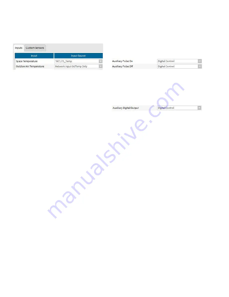
a. Select Outdoor Air Temperature Input Source as
“Network Input OdTemp Only”. This step configures
the logical value for outdoor air temperature.
2.
Open the Accessory Loops Section
3.
From Outputs tab
a. Select “Analog Control” from the Modulating Output
pulldown
b. Configure the type of analog control from the menu
below
4.
From Inputs tab
a. Select a 20Kntc sensor from the Main Sensor Input
Source pulldown
NOTE: This is the sensor for the hot water tempera-
ture control loop.
b. Select “Main Application Output” from the Reset
Sensor pulldown
NOTE: Select “OdTempLogical” from the Input Name
pulldown
5.
From the Setpoints tab
a. Enter the desired design conditions (180 F hot water
at 10 F outdoor air) peripheral hot water tempera-
ture setpoint at design conditions in the Occupied
box
NOTE: The Standby and Unoccupied values are
ignored but can be set equal to the Occupied
setpoint to avoid confusion if desired
b. Enter the desired values to determine the hot water
setpoint based upon minimum and maximum out-
door temperatures.
NOTE: In the following example, the hot water tem-
perature will be 180 degrees when the outdoor
air temperature is 10 degrees or below and the
hot water temperature will be 100 degrees
when the outdoor air temperature is 65
degrees or above. When the outdoor tempera-
ture is between 10 and 65 degrees, the set-
point will follow the line defined by those points
Occupied Setpoint: 180,
Min Reset Sensor Value: 10,
Max Reset Sensor Value: 65
Min Reset Amount: 0,
Max Reset Amount: -80
6.
From Control Params tab
a. Choose the desired PID loop settings
7.
Assign the desired terminals from the Custom Wiring
tab
Lighting controlled from internal application occupancy
using pulse on/off relays
An accessory loop is not necessary for pulsed lighting control.
Select “Digital Control” for the Auxiliary Pulse On and Auxiliary
Pulse Off in the VAV Outputs tab and the assigned DO’s will
follow the effective occupancy of the controller. On the
Schedule configuration screen, you may choose whether the
Standby period is treated as occupied or unoccupied
Fan control
An accessory loop is not necessary for simple exhaust fan
control. Select “Digital Control” for the Auxiliary Digital Output
in the VAV Outputs tab and the assigned DO will follow the
effective occupancy of the controller. On the Schedule
configuration screen, you may choose whether the Standby
period is treated as occupied or unoccupied
FLOW BALANCING
Balancing using the Niagara Tool
The Niagara tool supports a custom view on the controller
which allows you to perform the following:
• Flow pressure zero calibration
• Two point calibration
• K factor calibration
• Heating coil water flow calibration
Note that the option to calibrate the reheat valve is available
only when Modulating Reheat is configured and similarly the
option to calibrate the peripheral heat valve is available only
when Peripheral Heat is configured.
Also note that the view allows you to view and edit some key
parameters like duct inlet area, K-Factor, occupied flow
setpoints etc that affect the air flow in the box. Review these
parameters and correct them if required before starting the
flow balancing procedure.
Procedure for air flow balancing:
a. Flow pressure zero calibration:
To start zero balancing, click 'Start Zero Balancing'. The tool
commands the controller to completely close the damper and
waits till the damper position reports 0%. At this point, if any
flow pressure is detected, then that value is considered to be
the flow pressure offset. The tool reads the flow pressure from
the controller and updates the pressure offset accordingly.
After the completion of zero balancing, the device mode is set
to automatic operation.
b. Two point calibration
You can start either maximum or minimum balancing in any
order. The tool does not enforce any rules on the order of
balancing.
To start maximum calibration click 'Start Maximum Balancing'.


