


4 - 28
MAN0443.P65 Issue 13 Aug 04
5701 Control System
05701-M-5001 A02279
CHAPTER 4 - INSTALLATION INSTRUCTIONS
13.3
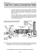
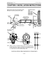
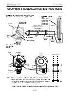
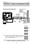
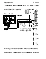
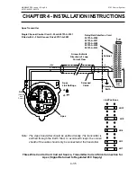
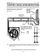
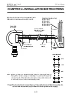
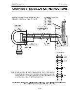
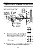
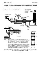
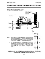
4 - 20mA Loop Powered Sensor Connections
Loop powered sensors require a two wire connection and the sensor
documentation will indicate the positive and negative loop connections,
usually brown and blue respectively.
At the System 57 end of the field cable the two sensor wires should
each be connected to one of either the S, 01 or NS terminals on the
Field Interface or Relay Card that is attached to the required Single
Channel Display Card. The two terminals used will vary depending
upon whether the location of the measuring resistance is in the loop
supply or return paths. Link options must also be set correctly on the 4
- 20mA Sensor Drive Module (see Section 12.3).
The sensor cable screen should be connected to the system earth.
This can be achieved at the Field Interface/Relay Card using the
GROUND terminal or where the cable enters the cabinet using a metal
cable gland, or by other suitable means.
Содержание 5701
Страница 1: ...Sieger System 57 5701 Control System Operating Instructions ...
Страница 45: ...2 32 MAN0443 P65 Issue 13 Aug 04 5701 Control System 05701 M 5001 A02279 CHAPTER 2 SYSTEM DESCRIPTION ...
Страница 63: ...3 18 CHAPTER 3 CONTROLS AND FACILITIES MAN0443 P65 Issue 13 Aug 04 5701 Control System 05701 M 5001 A02279 ...
Страница 139: ...4 76 MAN0443 P65 Issue 13 Aug 04 5701 Control System 05701 M 5001 A02279 CHAPTER 4 INSTALLATION INSTRUCTIONS ...
Страница 173: ...6 12 MAN0443 P65 Issue 13 Aug 04 5701 Control System 05701 M 5001 A02279 CHAPTER 6 OPERATING INSTRUCTIONS ...
Страница 209: ...9 4 MAN0443 P65 Issue 13 Aug 04 5701 Control System 05701 M 5001 A02279 CHAPTER 9 ORDERING INFORMATION ...


