5 - 5
MAN0443.P65 Issue 13 Aug 04
5701 Control System
05701-M-5001 A02279
CHAPTER 5 - COMMISSIONING AND
MAINTENANCE INSTRUCTIONS
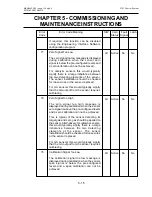
(14) Check the operation of the connected sensor by checking the
BEAD mA and mV SIGNAL for a catalytic sensor or the mA SIGNAL
for a 4 - 20mA sensor.
(15) Repeat Steps (11) to (14) for the remaining control cards in the
rack.
(16) Reconnect the terminal block TB2 to the DC Input Card and test the
optional Engineering Card module in accordance with the relevant
operating manual instructions.
(17) Verify the alarm configuration for each channel using the relay test
procedure outlined in Chapter 7 Section 6.
(18) Verify that the System 57 Control Cards and power supply are
operating within the maximum specified operating temperature
of 55
C.
ο
Содержание 5701
Страница 1: ...Sieger System 57 5701 Control System Operating Instructions ...
Страница 45: ...2 32 MAN0443 P65 Issue 13 Aug 04 5701 Control System 05701 M 5001 A02279 CHAPTER 2 SYSTEM DESCRIPTION ...
Страница 63: ...3 18 CHAPTER 3 CONTROLS AND FACILITIES MAN0443 P65 Issue 13 Aug 04 5701 Control System 05701 M 5001 A02279 ...
Страница 139: ...4 76 MAN0443 P65 Issue 13 Aug 04 5701 Control System 05701 M 5001 A02279 CHAPTER 4 INSTALLATION INSTRUCTIONS ...
Страница 173: ...6 12 MAN0443 P65 Issue 13 Aug 04 5701 Control System 05701 M 5001 A02279 CHAPTER 6 OPERATING INSTRUCTIONS ...
Страница 209: ...9 4 MAN0443 P65 Issue 13 Aug 04 5701 Control System 05701 M 5001 A02279 CHAPTER 9 ORDERING INFORMATION ...


