3 - 11
CHAPTER 3 CONTROLS AND FACILITIES
MAN0443.P65 Issue 13 Aug 04
5701 Control System
05701-M-5001 A02279
2.3
LEDS
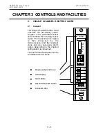
Five LEDs on the front panel of the control card indicate the operational
status of the channel as follows:
a.
FAULT
- Amber LED
The fault LED provides an indication in the event of a sensor hardware
failure, if the sensor signal is outside pre-defined limits or if the
channel card has detected a hardware or software fault.
b.
INHIBIT
- Amber LED
The inhibit LED indicates when the channel is in the inhibit condition.
This condition can be selected manually and remotely, or occurs
automatically:
during start-up for a pre-defined period of approximately 30
seconds,
when carrying out certain engineering functions such as zero,
span, 1st span and alarm test.
Depending upon the configuration, the control card may enter
the inhibit mode for a short period of time immediately after a
fault condition is cleared
During the inhibit condition, the channel card will continue to read the
gas sensor reading, however, no action is taken in the event of an
alarm condition being exceeded.
c.
A1
- Red LED
The A1 LED indicates that the preset first level gas alarm has been
exceeded. This alarm will not function in the event of either a fault or
inhibit condition being active.
d.
A2
- Red LED
The A2 LED indicates that the preset second level gas alarm has
been exceeded. This alarm will not function in the event of either a
fault or inhibit condition being active.
e.
A3
- Red LED
The A3 LED indicates that the preset third level gas alarm has been
exceeded. This alarm will not function in the event of either a fault or
inhibit condition being active.
Содержание 5701
Страница 1: ...Sieger System 57 5701 Control System Operating Instructions ...
Страница 45: ...2 32 MAN0443 P65 Issue 13 Aug 04 5701 Control System 05701 M 5001 A02279 CHAPTER 2 SYSTEM DESCRIPTION ...
Страница 63: ...3 18 CHAPTER 3 CONTROLS AND FACILITIES MAN0443 P65 Issue 13 Aug 04 5701 Control System 05701 M 5001 A02279 ...
Страница 139: ...4 76 MAN0443 P65 Issue 13 Aug 04 5701 Control System 05701 M 5001 A02279 CHAPTER 4 INSTALLATION INSTRUCTIONS ...
Страница 173: ...6 12 MAN0443 P65 Issue 13 Aug 04 5701 Control System 05701 M 5001 A02279 CHAPTER 6 OPERATING INSTRUCTIONS ...
Страница 209: ...9 4 MAN0443 P65 Issue 13 Aug 04 5701 Control System 05701 M 5001 A02279 CHAPTER 9 ORDERING INFORMATION ...

