


7 - 17
MAN0443.P65 Issue 13 Aug 04
5701 Control System
05701-M-5001 A02279
CHAPTER 7 - ENGINEER'S OPERATING
INSTRUCTIONS
11.
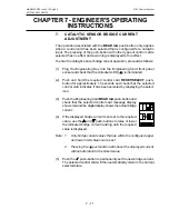
SENSOR SIGNAL MONITORING
The operation of the
SIGNAL
push-button allows the monitoring of the
selected channels sensor signal value. The displayed parameter is
dependent upon the type of sensor drive module fitted to the selected
channel card.
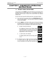
To enter the sensor signal monitoring operation, proceed as follows:
(1)
Push and hold the required channel card
RESET/SELECT
push-
button for approximately 1.5 seconds until the selected icon appears
on the channel display.
(2)
Push the
SIGNAL
push-button and the selected channel card display
will indicate the sensor signal. The displayed value will depend on the
type of sensor drive module fitted to the channel card as follows:
a.
Catalytic Sensor Drive Module
The display will show the live bridge voltage
measured between 01 and 02 in mV. 02 is the
centre point of the second half of the Wheatstone
bridge which is on the channel card.
b.
4 - 20mA Sensor Drive Module
The display will show the live sensor loop current
in mA.
(3)
No alterations can be made to the above readings
and pressing either the or push-buttons will
return the selected control card to the selected mode.
Содержание 5701
Страница 1: ...Sieger System 57 5701 Control System Operating Instructions ...
Страница 45: ...2 32 MAN0443 P65 Issue 13 Aug 04 5701 Control System 05701 M 5001 A02279 CHAPTER 2 SYSTEM DESCRIPTION ...
Страница 63: ...3 18 CHAPTER 3 CONTROLS AND FACILITIES MAN0443 P65 Issue 13 Aug 04 5701 Control System 05701 M 5001 A02279 ...
Страница 139: ...4 76 MAN0443 P65 Issue 13 Aug 04 5701 Control System 05701 M 5001 A02279 CHAPTER 4 INSTALLATION INSTRUCTIONS ...
Страница 173: ...6 12 MAN0443 P65 Issue 13 Aug 04 5701 Control System 05701 M 5001 A02279 CHAPTER 6 OPERATING INSTRUCTIONS ...
Страница 209: ...9 4 MAN0443 P65 Issue 13 Aug 04 5701 Control System 05701 M 5001 A02279 CHAPTER 9 ORDERING INFORMATION ...


