2 - 2
MAN0443.P65 Issue 13 Aug 04
5701 Control System
05701-M-5001 A02279
CHAPTER 2 - SYSTEM DESCRIPTION
CONTENTS
Section
Page
1.
INTRODUCTION
2-3
2.
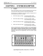
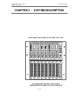
RACKS
2-4
3.
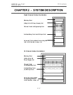
CABINETS
2-6
4.
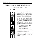
SINGLE CHANNEL CONTROL CARDS
2-8
4.1
General
2-8
4.2
Single Channel Control Card
2-9
4.3
Sensor Drive Modules
2-9
4.4
Analogue Output Module
2-9
4.5
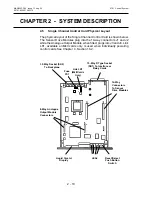
Single Channel Control Card Physical Layout
2-10
5.
FIELD INTERFACE AND RELAY CARDS
2-11
5.1
General
2-11
5.2
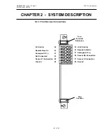
Field Interface Card
2-11
5.3
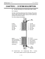
Double SPCO Relay Card
2-14
5.4
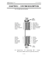
Triple SPCO Relay Card
2-16
5.5
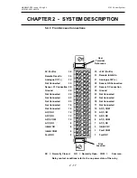
Triple DPCO Relay Card
2-18
5.6
High Integrity Relay Card
2-20
6.
ENGINEERING CARD
2-23
7.
DC INPUT CARD
2-25
7.1
General
2-25
7.2
Rear Access Connections
2-26
7.3
Front Access Connections
2-27
8.
AC TO DC POWER SUPPLY UNITS
2-28
8.1
Types of Power Supply Unit
2-28
8.2
Power Supply Unit Upgrades
2-28
8.3
Power Supply Connections
2-28
8.4
8-Way AC to DC Power Supply Unit Layout
2-29
8.5
16-Way AC to DC Power Supply Unit Layout
2-29
8.6
50W Sub-Unit Layout
2-30
8.7
100W Sub-Unit Layout
2-30
9.
FRONT PANEL BLANKING PANEL
2-31
Содержание 5701
Страница 1: ...Sieger System 57 5701 Control System Operating Instructions ...
Страница 45: ...2 32 MAN0443 P65 Issue 13 Aug 04 5701 Control System 05701 M 5001 A02279 CHAPTER 2 SYSTEM DESCRIPTION ...
Страница 63: ...3 18 CHAPTER 3 CONTROLS AND FACILITIES MAN0443 P65 Issue 13 Aug 04 5701 Control System 05701 M 5001 A02279 ...
Страница 139: ...4 76 MAN0443 P65 Issue 13 Aug 04 5701 Control System 05701 M 5001 A02279 CHAPTER 4 INSTALLATION INSTRUCTIONS ...
Страница 173: ...6 12 MAN0443 P65 Issue 13 Aug 04 5701 Control System 05701 M 5001 A02279 CHAPTER 6 OPERATING INSTRUCTIONS ...
Страница 209: ...9 4 MAN0443 P65 Issue 13 Aug 04 5701 Control System 05701 M 5001 A02279 CHAPTER 9 ORDERING INFORMATION ...

