3 - 14
CHAPTER 3 CONTROLS AND FACILITIES
MAN0443.P65 Issue 13 Aug 04
5701 Control System
05701-M-5001 A02279
3.
ENGINEERING CARD
3.1
General
The Engineering Card provides facilities to allow each control card to be
interrogated and to allow normal maintenance functions such as
calibration to be carried out. It also acts as a connecting point for the
engineering interface which allows each card to be configured.
3.2
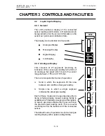
LED Indicators
Two indicators at the top of the front panel of the
Engineering Card indicate the operational status of
the card:
3.2.1
- Green LED
A continuously illuminated LED indicates that the
correct dc power is connected to the rack via the DC
Input Card.
A flashing LED at approximately two second intervals,
indicates a low dc power input level.
A flashing LED at approximately 0.5 second intervals,
indicates a hardware fault.
3.2.2
- Red LED
Provides an indication of the operation of the
Engineering Card communications status as follows:
Off:
Engineering Card functioning correctly and
the engineering functions are locked.
Operators functions are operational to allow
the checking of various control card settings.
On:
Engineering Card functioning correctly and
the engineering functions are unlocked
enabling changes to be made to the
operation of a selected control card.
Flashing: Indicates that a control card has been
withdrawn from the rack, there is a
communications error or that an external
PC running the engineering interface
software is communicating with the control
cards.
Note: To reset this indication, insert the Engineering
Key briefly and remove it again.
CLOCK
INHIBIT
1
ST
SPAN
SPAN
SIGNAL
ZERO
ALARMS
BEAD mA
Содержание 5701
Страница 1: ...Sieger System 57 5701 Control System Operating Instructions ...
Страница 45: ...2 32 MAN0443 P65 Issue 13 Aug 04 5701 Control System 05701 M 5001 A02279 CHAPTER 2 SYSTEM DESCRIPTION ...
Страница 63: ...3 18 CHAPTER 3 CONTROLS AND FACILITIES MAN0443 P65 Issue 13 Aug 04 5701 Control System 05701 M 5001 A02279 ...
Страница 139: ...4 76 MAN0443 P65 Issue 13 Aug 04 5701 Control System 05701 M 5001 A02279 CHAPTER 4 INSTALLATION INSTRUCTIONS ...
Страница 173: ...6 12 MAN0443 P65 Issue 13 Aug 04 5701 Control System 05701 M 5001 A02279 CHAPTER 6 OPERATING INSTRUCTIONS ...
Страница 209: ...9 4 MAN0443 P65 Issue 13 Aug 04 5701 Control System 05701 M 5001 A02279 CHAPTER 9 ORDERING INFORMATION ...

