


MAN0443.P65 Issue 13 Aug 04
5701 Control System
05701-M-5001 A02279
CHAPTER 4 - INSTALLATION INSTRUCTIONS
4 - 25
13.
SENSOR CONNECTIONS
13.1
General
WARNING
Incorrect connection of the sensor wires may cause damage to
both the sensor and System 57.
CAUTION
The sensors connections must always be made with the System
57 unit in an unpowered state. Isolate power supplies at their
source before making connections.
Ensure that any external dc backup battery supply is also
disabled.
IMPORTANT
In order to ensure the correct operation of the system and to
meet European Standards for RFI and EMC, all sensor field
cables must be screened. The cable screen of each sensor
should be connected to the cabinet protective earth.
Connect the cabling to sensors in accordance with the Sensor Operating
Instructions and run the field cables back to the System 57 unit. The
sensor cables should be routed away from sources of interference
such as ac power cables, motors, machinery etc.
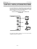
Use the information on the configuration sheet provided with the unit
to decide which sensor to connect to each channel. The following
sections describe the sensor connections for the Catalytic and 4 - 20mA
input Single Channel Control Cards.
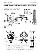
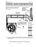
13.2
Catalytic Sensor Connections
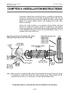
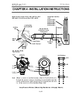
Catalytic sensors require a three wire connection and the sensor
documentation will indicate three connections S, 01 and NS, which are
usually brown, white and blue respectively. In addition, the SensePoint
combustible ppm version also has a screen connection.
At the System 57 end of the field cable, the three sensor wires should
each be connected to the respective matching S, 01 or NS terminal on
the Field Interface or Relay Card that is attached to the required Single
Channel Display Card.
Содержание 5701
Страница 1: ...Sieger System 57 5701 Control System Operating Instructions ...
Страница 45: ...2 32 MAN0443 P65 Issue 13 Aug 04 5701 Control System 05701 M 5001 A02279 CHAPTER 2 SYSTEM DESCRIPTION ...
Страница 63: ...3 18 CHAPTER 3 CONTROLS AND FACILITIES MAN0443 P65 Issue 13 Aug 04 5701 Control System 05701 M 5001 A02279 ...
Страница 139: ...4 76 MAN0443 P65 Issue 13 Aug 04 5701 Control System 05701 M 5001 A02279 CHAPTER 4 INSTALLATION INSTRUCTIONS ...
Страница 173: ...6 12 MAN0443 P65 Issue 13 Aug 04 5701 Control System 05701 M 5001 A02279 CHAPTER 6 OPERATING INSTRUCTIONS ...
Страница 209: ...9 4 MAN0443 P65 Issue 13 Aug 04 5701 Control System 05701 M 5001 A02279 CHAPTER 9 ORDERING INFORMATION ...


